A good cell is where a stack starts, not where it ends. Once cells are assembled, compression, flow, electrical contact and thermal conditions decide how much of that cell performance survives.
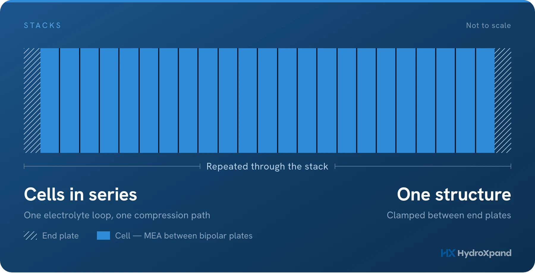
A good electrolysis cell is the starting point for a good stack. It is not the whole story.
Once multiple cells are assembled into a stack, they begin to share mechanical compression, flow paths, electrical interfaces, and a common thermal environment. At that point, performance is no longer determined by the electrochemical components alone.
The challenge becomes reproducing good cell performance across the entire stack, and keeping it there over time.
What is an electrolyzer stack?
A single electrolysis cell typically operates at only a few volts. To reach a practical power level, multiple cells are electrically connected in series and assembled into one structure. That assembly is the electrolyzer stack.
From the outside, a stack can look like a repeated set of identical cells held between two end plates. But simply repeating a good cell does not guarantee a good stack.
Each cell must operate under sufficiently similar conditions. That means maintaining consistent compression, fluid distribution, electrical contact, temperature, and sealing throughout the assembly. Small differences in any of these can become visible as differences in cell performance.
This is where stack engineering begins.
What is inside a stack?
An electrolyzer stack is made up of electrochemical components together with the structures that connect, supply, seal, and compress them.
- Membrane electrode assembly. The membrane and catalyst layers where the electrochemical reactions take place. Their properties strongly influence the efficiency and performance available at the cell level.
- Porous transport layer. Provides electrical contact while allowing reactants and products to move between the electrode and the surrounding flow structure. Electrical conduction and mass transport have to be balanced at the same time.
- Bipolar plate. Separates adjacent cells, conducts current between them, and provides the flow field used to distribute fluids over the active area.
- Seals. Keep gases and liquids within their intended paths and maintain separation between different regions of the cell.
- Compression structure. Holds the repeated cell assembly together and maintains the mechanical load required for electrical contact, sealing, and dimensional stability.
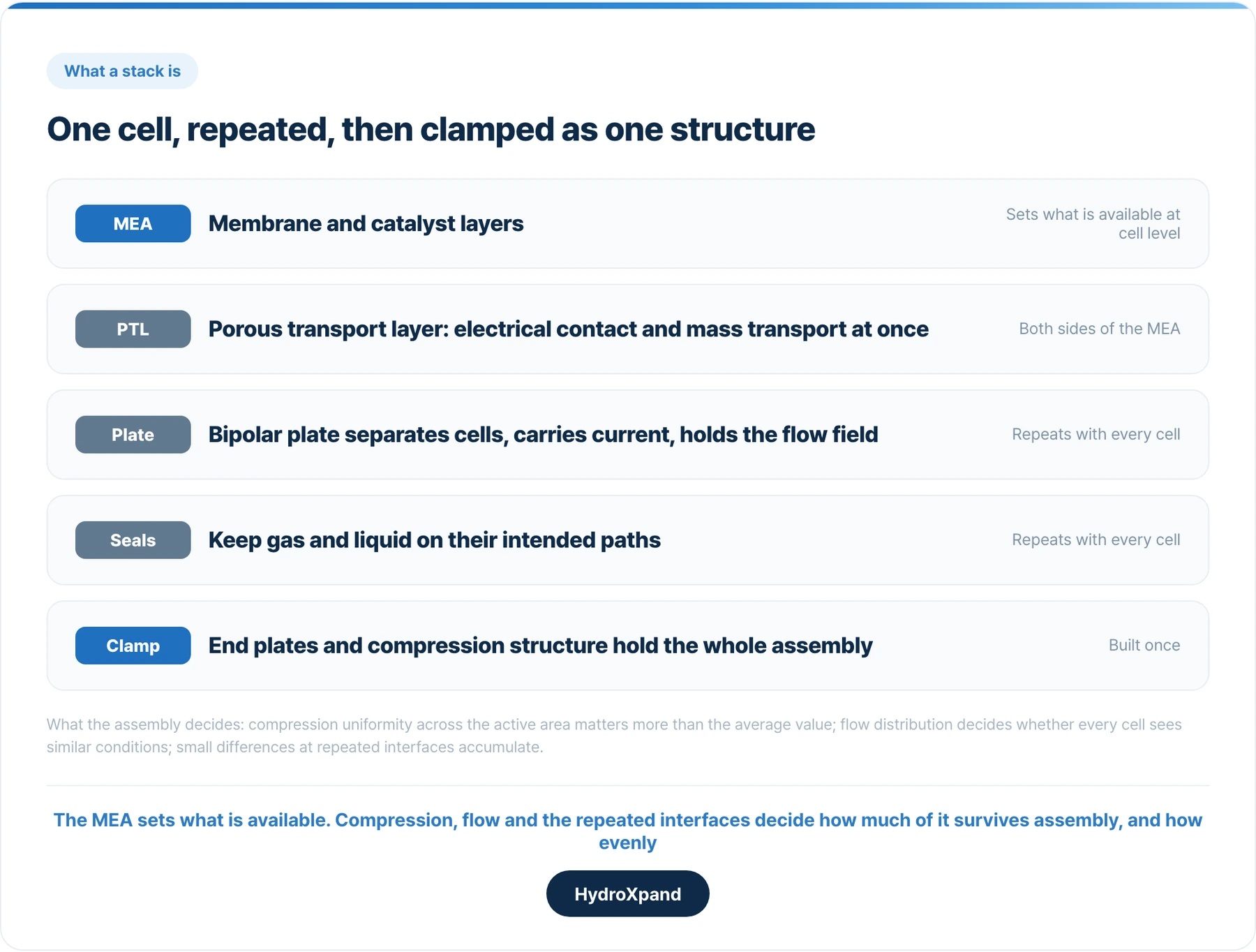
None of these components works independently. Changing the compression can affect electrical contact and porous structures. Changing the flow field can affect temperature and gas removal. Changing one interface can alter the mechanical condition of another.
A stack therefore has to be treated as an integrated structure rather than a collection of separate components.
- AEM stack hardware parts→Bipolar plates, gaskets and end plates for HXS stacks, orderable individually.
- AEM electrolyzer stack integration guide→What a stack needs from your balance of plant: electrolyte loop, ports, heat load and commissioning.
- Buy the 2 kW AEM stack→HXS-2: 23 cells, 1 kg of hydrogen per day, available to order.
Stack components, part by part
Every part named above can be bought on its own. The table lists the materials we use in our own stacks, as published on the parts and product pages.
| Part | What it does | In our stacks |
|---|---|---|
| Bipolar plate | Separates cells, carries current, distributes the flow | Nickel-based metallic platepure Ni, titanium or Pt-coated titanium on request |
| Gaskets | Keep gas and electrolyte in their paths | EPDM set on HXS-2 and HXS-30PTFE or FEP film on HXS-0 |
| End plates | Hold the compression across the whole cell stack | SUS316Ltitanium, SUS304 or steel on request |
| Anode | Oxygen evolution | HXP-anNiFe LDH grown on nickel foam, no precious metal |
| Cathode | Hydrogen evolution | HXP-caPt/C or PtRu/C on carbon paper, 0.2 mgPGM/cm² |
| Membrane | Separates the gases and conducts OH⁻ | Anion exchange membranesupplied in small quantities |
| Porous transport layer | Electrical contact plus a path for liquid and gas | Porous nickel on the anode side |
Changing a material changes more than the part. Published performance data applies to the stack as built, which is why a material change comes with its own validation scope.
- Stack hardware: bipolar plates, gaskets, end plates→Orderable individually or as a set matched to your stack and cell count.
- AEM membranes→The membranes we use in our own stacks, in small quantities.
- Ionomer→The polymer that binds a particulate catalyst layer and carries ions inside it.
- Nickel substrates and porous transport layers→The porous metal our anodes are grown on.
How cell count scales output
Cells in a stack are connected in series, so the same current passes through every one of them. Each cell makes hydrogen in proportion to that current, which means that at a given current the stack's hydrogen output and its voltage both rise with the number of cells.
That gives a stack designer two levers. Cell area sets how much current each cell can carry at a sensible current density. Cell count multiplies whatever one cell produces.
| HXS-30 stage | Spread across all cells (max − min) | Conditions |
|---|---|---|
| 5 cellsJune 2026 | 15 mV1.615 to 1.630 V | About 360 A · electrolyte 60 °C |
| 15 cells26 August 2026 | 40 mVmean 1.664 V, σ 9.6 mV | 360 A · 0.1 M KOH · 50 °C · first run |
| 46 cellsSeptember 2026 | 33.7 mV1.658 V per cell | About 360 A · 0.1 M KOH · 50 °C · start of the first long-run record |
Adding cells is a problem of assembly and uniformity. Growing the cell area changes what happens inside the cell.
More cells is also where the difficulty lies. When we built the HXS-30 we added cells in steps and measured every cell at each step, because the spread between the best and worst cell is the number that grows with cell count.
- Scaling an AEM stack from 79 cm² to 512 cm²→The technical note behind the 5- and 15-cell rows, including what went wrong first.
- The 46-cell HXS-30 full stack→The first long-run record of the full stack, with every cell voltage.
- Parallel units or a larger stack→When to repeat a small stack and when to move up to a larger one.
What changes when a cell becomes a stack?
Active area becomes a distribution problem
Increasing active area does more than increase the current that a cell can carry. It also increases the distance over which fluids, current, heat, and mechanical load must be distributed uniformly.
A larger cell is therefore not simply a smaller cell scaled geometrically. Maintaining similar conditions over the entire active area becomes a design problem of its own.
Compression has to be uniform
A stack needs enough compression to maintain electrical contact and sealing, but more compression is not automatically better.
Too little can increase contact resistance or reduce sealing reliability. Too much can deform components and change transport through porous structures.
The average compression value alone is not enough. What matters is how evenly that load is distributed over the active area and maintained throughout the stack.
Flow has to reach every region consistently
The average flow rate entering a stack does not tell you how that flow is distributed internally. Each cell, and each part of each cell, should receive sufficiently similar operating conditions.
Poor distribution can create local differences in concentration, temperature, gas removal, and pressure. Those local differences can eventually appear as differences in voltage or degradation.
Repeated interfaces amplify small variations
A single test cell contains only a limited number of interfaces. A stack repeats those interfaces many times.
Small differences in component thickness, surface contact, sealing, or assembly that may be difficult to notice in one cell can accumulate or become more important when repeated throughout a stack.
Average performance is not the whole picture
A stack can have a reasonable average voltage while individual cells behave differently. That is why cell-to-cell consistency matters.
A weak or abnormal region can influence operating limits, efficiency, gas quality, or durability even when the overall stack number still looks acceptable.
For stack validation, understanding the spread within the stack can therefore be as important as understanding the average.
Why single-cell results do not automatically scale
Single-cell testing is essential. It allows membranes, electrodes, catalysts, interfaces, and operating conditions to be studied under controlled conditions. But it answers a different question from stack testing.
- A single-cell result asks: can this electrochemical configuration perform well?
- A stack test asks: can that performance be reproduced across a multi-cell assembly?
- Manufacturing adds a third question: can the same stack performance be reproduced from unit to unit?
A strong single-cell result is important, but it is not sufficient evidence of a mature stack.
These are different stages of development. Moving from the first to the second introduces flow distribution, compression uniformity, repeated interfaces, electrical contact, thermal gradients, and cell-to-cell variation.
Moving from the second to the third introduces manufacturing tolerances, assembly repeatability, and quality control.
Durability also changes meaning at stack level
Durability is often presented as a single degradation rate. But that number only becomes useful when the conditions behind it are known. Current or current density, temperature, fluid conditions, pressure, test duration, and the basis used to calculate degradation all matter.
Stack durability adds another layer: whether all parts of the stack are aging in a similar way.
A stable average voltage does not necessarily mean every cell is behaving identically, just as a change in stack voltage does not by itself explain where the change originated. Long-term stack validation therefore needs both time and context.
What should an electrolyzer stack datasheet tell you?
A useful datasheet should allow the reader to understand not only what performance was measured, but under what conditions.
- Active area
- Rated current and voltage
- Rated hydrogen production
- Operating temperature
- Fluid or electrolyte conditions
- Operating pressure range
- Gas purity or crossover information where relevant
- Efficiency and the basis used to calculate it
- Durability or degradation data with the corresponding test conditions
The operating conditions are not footnotes. An efficiency measured at one temperature or operating point cannot be compared directly with a number measured somewhere else under different conditions.
The same is true for degradation. A durability number without the current, temperature, pressure, test duration, and other relevant operating conditions is difficult to interpret.
It is also useful to know whether a result comes from a single cell, a short stack, or a full stack. The larger the test object becomes, the more of the actual stack engineering is included in the result.
Stack vs system
A stack only makes hydrogen when something supplies it with DC power, water and electrolyte at the right temperature, takes the gases away and watches the whole process. That surrounding equipment is the balance of plant, and a stack plus its balance of plant is an electrolysis system.
The difference shows up in the energy figures. Our HXS-2 stack uses 44 kWh per kilogram of hydrogen. The complete HXB-V1 system built around it uses 56 kWh/kg, and the gap of about 12 kWh/kg is the balance of plant. A stack number and a system number are therefore different claims, and should be compared only with their own kind.
Status and targets are consistent with an end-of-life performance loss of 10%.
SourcesU.S. DOE Technical Targets for Liquid Alkaline Electrolysis: separate stack and system energy rows (2022 status 51 and 55 kWh/kg) · U.S. DOE Technical Targets for PEM Electrolysis
- Electrolyzer system vs stack→What the balance of plant adds, and why system efficiency is not stack efficiency.
- HXB-V1 · 2 kW turnkey system→The HXS-2 stack with its balance of plant in one rack.
Integrating a stack into your own plant
Buying a bare stack moves the balance of plant to your side of the boundary. For the HXS-2 that means a DC supply sized for the operating current range, an electrolyte circulation loop and pump at a standard 4 L/min, cooling and temperature control, gas-liquid separation, outlet piping with vent and drain, instrumentation, control and site hydrogen safety.
None of these is unusual, but each has limits the stack sets: the ports, the heat load, the pressure the stack is rated for and the sequence for commissioning it. Those are written down in the integration guide, so the design can start from them rather than discover them.
- AEM electrolyzer stack integration guide→Electrolyte loop sizing, ports, heat load, pressure limits and commissioning for the HXS-2.
- Balance of plant: what an electrolyzer stack needs around it→Power, water, electrolyte, gas handling, instrumentation and safety, loop by loop.
- Putting an electrolyzer inside your own plant→What you can set, read and connect.
- Electrolyte circulation parts→The pump build that survives hot KOH, specified for your loop.
Buying an electrolyzer stack: from test cell to 30 kW
At HydroXpand, we work across several stages of AEM water electrolyzer development.
HXS-0 is our test-cell platform for evaluating membranes, electrodes, catalysts, and other electrochemical components over a range of active areas.
HXS-2 is our 2 kW-class AEM water electrolyzer stack, available to order for integration with your own balance of plant. The product page provides operating conditions, performance and durability data, interface details and current lead time.
HXS-30 is our 30 kW-class stack. The 46-cell full stack, designed for 6,900 NL/h (15 kg/day), is available to order now; it completed first operation in September 2026 and is currently under long-term evaluation.
These platforms address different questions, but they are part of the same development path. A test cell tells us whether an electrochemical concept works. A multi-cell stack tells us whether that performance can be reproduced across a larger assembly. Long-term operation tells us whether it can be maintained. And repeated builds tell us whether it can be manufactured consistently.
Good cell performance is where stack development starts.
Making that performance uniform, durable, and repeatable is what turns it into stack engineering.
- Buy the 2 kW AEM stack (HXS-2)→Review the stack specifications, integration requirements and current lead time.
- HXS-2 stack integration guide→Electrolyte loop sizing, ports, heat load and pressure limits for your own BoP.
- HXS-30 · 30 kW-class stack→The 46-cell full stack is available now, under long-term evaluation after first operation.
- HXS-0 · test cell→For evaluating customer-supplied catalysts, electrodes and membranes.
- What an electrolysis system is→One level up: the balance of plant around the stack, and why system efficiency is not stack efficiency.
- What is an MEA→The component inside every cell in that stack, and what decides whether it is any good.
- Datasheets→Six products in English, no form.
- Cell voltage distribution→What one stack voltage hides, and what to ask a supplier for.
- AEM electrolysis: technology and measured data→How AEM electrolysis works, what is inside the cell, and the data behind our stacks.
- Electrolyzer efficiency explained→Why a stack figure and a system figure are not the same number.
- Is AEM electrolysis proven?→What has been demonstrated at stack level, with hours and conditions.
- Sizing: parallel units or a larger stack→When to repeat a small stack and when to move up a grade.
Frequently asked questions
What is an electrolyzer stack?
A stack is a set of cells assembled between end plates and compressed so that current, electrolyte and gas are shared across all of them. Compression, flow distribution and electrical contact decide how much of the single-cell performance survives.
Why do single-cell results not scale directly to a stack?
Because active area becomes a distribution problem, compression has to be uniform, and repeated interfaces amplify small variations. A strong single-cell result is necessary but not sufficient evidence of a mature stack.
What should an electrolyzer stack datasheet tell you?
The operating conditions behind every figure, the cell-to-cell voltage spread rather than only the average, and durability stated at stack level with hours and conditions.
How does the number of cells change a stack's output?
Cells are connected in series, so the same current passes through every one and, at a given current, hydrogen output and stack voltage rise with cell count. Our HXS-2 uses 23 cells of 79 cm² for 2 kW; the HXS-30 uses 46 cells of 512 cm² for the 30 kW class.
What is the difference between an electrolyzer stack and a system?
The stack is the set of cells where electrolysis happens; the system adds the balance of plant that supplies power, water and electrolyte and handles the gases. Our HXS-2 stack uses 44 kWh/kg of hydrogen and the complete HXB-V1 system 56 kWh/kg.
Sources
- Technical Targets for Liquid Alkaline Electrolysis — U.S. Department of Energy
- Technical Targets for Proton Exchange Membrane Electrolysis — U.S. Department of Energy
Looking at AEM for a specific application?