A stack connected to a power supply does not make hydrogen. It needs the right DC current, water of a set quality, electrolyte at a steady temperature, somewhere to send wet gas, and something watching all of it. That surrounding equipment is the balance of plant. This is what each part has to decide, written for teams building it around a bare stack.
Balance of plant, usually shortened to BoP, is a term electrolysis borrowed from power generation. In a power station it meant everything apart from the turbine and generator. In an electrolyzer it means everything apart from the stack.
The stack is where water is split, and it is a fairly small object. Our 2 kW stack, the HXS-2, is 190 × 198 × 215 mm and 19 kg. The rectifier, pump, tank, separators, heat exchanger and sensors around it take most of the space and most of the maintenance list, which budgets built on stack specifications tend to discover late.
This is written for teams building that equipment around a bare stack. How BoP changes the efficiency figure is covered in our piece on system versus stack.
Five loops around one stack
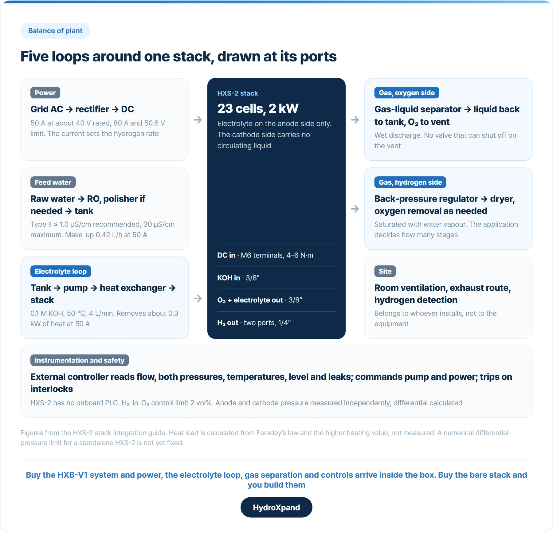
The work splits into five groups: power, feed water treatment, the electrolyte loop, gas handling, and instrumentation with safety.
Stack performance and BoP design are separate problems. The same stack gives different purity and different safety margins depending on how these five are built.
A stack with good numbers and no BoP is a component. It becomes a plant when the other five pieces are in place.
Power: the current is the production rate
The stack runs on DC, so a rectifier sits in front of it. That supply also sets the current, and hydrogen output follows the current, so turning production up or down is a command to the power supply.
For the HXS-2 the rated point is 50 A at about 40 V at beginning of life, and the operating limit is 80 A and 50.6 V, which is 2.2 V per cell across 23 cells. Size the supply to that range, and size cable for 50 A continuous. The DC terminals are M6 and take 4 to 6 N·m; more than that damages them.
Conversion loss lands in the system figure rather than the stack figure, one reason the two differ.
Water and electrolyte are two loops, not one
Feed water is not tap water; dissolved ions and organics build up on the electrodes and membrane. Our recommendation is ASTM D1193 Type II, at or below 1.0 µS/cm, and the maximum we work to is 30 µS/cm. That difference decides the plant: at 30 µS/cm most sites finish with a single reverse osmosis unit, and meeting 1.0 µS/cm adds an ion-exchange polisher behind it. Filters and resin are consumables, and their replacement interval depends on the raw water.
The electrolyte loop is a different circuit. On the HXS-2 dilute KOH circulates on the anode side only, in parallel to every cell, at a standard 4 L/min. The stack alone drops about 0.11 bar at that flow; we use 0.3 bar of available head as a preliminary pump figure before piping losses are added.
The same loop carries heat out: roughly 0.3 kW at 50 A and 1.3 kW at 80 A, so a 1.5 kW class heat exchanger leaves margin. At low current the electrolyte will not reach temperature on its own, and long low-current operation needs a tank heater.
Uneven circulation shows up as a spread in cell voltages. That is one reason to ask for per-cell voltage data alongside stack figures.
SourceASTM D1193-06(2018) Standard Specification for Reagent Water, Type II
Gas handling: fit what the application asks for
The two outlets leave the stack in different states. The anode outlet carries oxygen and electrolyte together, so it goes through gas-liquid separation, the liquid returns to the tank and the oxygen is vented. On the HXS-2 no electrolyte circulates on the cathode side, so the hydrogen outlet does not carry the loop's liquid. It is still saturated with water vapour and carries a trace of oxygen.
What comes next depends on the use. A dryer lowers the dew point; a catalytic stage turns the remaining oxygen into water. Fuel cell testing usually needs both, a furnace atmosphere often neither. On our HXB-V1 system, purity is 98 to 99% without a dryer at ambient pressure and 99.999% or better with one. Our own dryer, HXD-V1, is in development.
Adding stages the application does not need raises cost twice, once on the purchase and again in power and maintenance.
Instrumentation and safety have two owners
Hydrogen in oxygen matters most. We manage it below 2 vol% and recommend stopping to inspect above that. Anode and cathode pressures need independent transmitters and a calculated differential, because a widening difference stresses the membrane. Leak detection is tied through interlocks to the power supply and valves.
Two rules from our integration guide are easy to miss. No valve that can shut off may sit on a vent line, including the tank vent. And 10 barg is the maximum hydrogen-side pressure, not an allowable differential of 10 bar; a numerical differential limit for a standalone HXS-2 is not yet fixed, and we say so in the guide.
Instrumentation and interlocks inside the equipment belong to whoever builds it. Room ventilation, exhaust and site hydrogen detection belong to whoever installs it. Agree who does what before delivery.
| Loop | Bare HXS-2 | HXB-V1 system | Site |
|---|---|---|---|
| Power | You build: DC supply for 50 A, up to 80 A | Built in200 to 240 V AC single phase in | Circuit and supply work |
| Feed water | You build: treatment to spec | Top-up built in | Water treatment and tank |
| Electrolyte loop | You build: pump, tank, heat exchanger | Built inKOH 0.1 to 1 M, 2 to 5 L/min | Nothing |
| Gas handling | You build: separator, BPR, drying | Separators built indryer optional | Downstream use and storage |
| Instruments and interlocks | You build: external controller | Built inH₂ detection, E-STOP | Room ventilation, exhaust, site detection |
SourceSandia National Laboratories: lower flammability limit of hydrogen in air, 4% mole fraction (the 2 vol% hydrogen-in-oxygen limit above is our operating limit, set well below it)
Four things to ask a stack supplier
A finished system arrives with the BoP inside; our 2 kW system is connected to power, water and vents and run. Buying the stack means building the BoP, with more design freedom. If the goal is hydrogen, a system is faster; if the goal is the system itself, buy the stack.
On the second route four questions come up every time, and how specifically a supplier answers them is a fair test.
- Interfaces. Port sizes and positions, DC terminals, and where each measurement is taken. On the HXS-2 these are a 3/8-inch electrolyte inlet, a 3/8-inch oxygen and electrolyte outlet, two 1/4-inch hydrogen ports and M6 DC terminals.
- Control. Whether the stack carries its own controller, or an external one reads the sensors and commands the pump and power supply. The HXS-2 has no onboard PLC, so the design starts by deciding what is read where.
- Interlocks. Which conditions must stop the stack and how that signal is exchanged. Trip settings for a standalone stack are fixed per project against the P&ID.
- Support. How far design review goes, whether the supplier attends commissioning, and what happens when something fails. We supply the HXS-2 for BoP integration and work to the specification with the customer from the design stage.
A quotation for the same hydrogen output can mean the stack, the stack with BoP, or both installed. Settle which before comparing numbers.
Installation and site safety sit on top of either route: exhaust path, ventilation, power supply works and hydrogen detection are part of the room, not the equipment, and are often missing from a quotation for that reason.
- What is an electrolyzer stack→What a stack is made of, how cell count scales output, and what decides performance.
- HXS-2 stack integration guide→Loop sizing, ports, heat load, interlocks and what is not fixed yet.
- 2 kW stack: what goes around it→The BoP components we specify and source for an HXS-2 build.
- Electrolyzer components and BoP→Every BoP part we source, listed in process order from feed water to compression.
- Water treatment for electrolyzer feed water→The pre-treatment train set from your source water and daily demand.
- Hydrogen dryer for electrolyzers→Drying and purification stages matched to the dew point and purity you need.
- System versus stack→Where BoP shows up in the efficiency figure, with our measured split.
- What turnkey includes in a 2 kW electrolyzer→The other route: where the supplied box stops.
- Before the electrolyzer arrives→The room-side half of the safety split: vent, clearance, power and water.
- What changes when you run the stack at 10 bar→Measured crossover against load and pressure, the data behind the interlock limits.
- HXS-2 · 2 kW stack→Full specification, datasheet and long-run data.
Frequently asked questions
What does balance of plant mean in an electrolyzer?
Everything apart from the stack: power conversion, feed water treatment, electrolyte circulation, gas handling, and instrumentation and safety. Stack plus BoP is the electrolysis system.
Does the balance of plant use electricity?
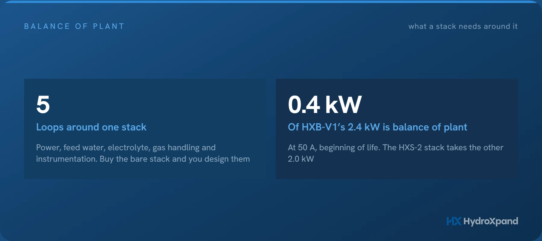
Yes. On HydroXpand's HXB-V1, the system draws 2.4 kW at 50 A, of which 2.0 kW goes to the stack and 0.4 kW to the balance of plant.
What should I ask a supplier before integrating a bare stack?
Ask about interfaces, control, interlocks and support: port and terminal details, whether an external controller runs the stack, which conditions trip it, and how far design review and commissioning support go.
Sources
- ASTM D1193-06(2018) Standard Specification for Reagent Water — ASTM International
- Flammability Limits of Hydrogen/air Mixtures, SAND2007-5365P — Sandia National Laboratories, via OSTI
Looking at AEM for a specific application?