Engineers integrating an electrolyzer into their own equipment ask about control before output. This walks through what our 2 kW system lets you set and record, how several units share one screen, how it talks to a site control system, and what changes when you buy only the stack.
Engineers planning to put an electrolysis system inside their own equipment tend to ask about control before they ask about output. What is fixed inside the unit, and what can be decided from outside it, changes how the rest of the plant gets designed.
Here is how that works on our 2 kW system, HXB-V1, and what changes when you buy the stack alone and build the control yourself.
Why a closed box stops working inside a plant
On its own, an electrolyzer needs little more than its front panel. Put it inside a larger installation and three more things are needed.
The plant has to be able to change the operating point, so the current setpoint must be writable from outside. It has to match the outlet pressure to the storage downstream. And it has to see the unit's measurements in its own supervisory system, which means the unit must send them out over a network.
A unit that offers none of these stays a separate machine, and someone still walks up to it to adjust it by hand. So the questions are which values can be read from outside, which can be written, and whether the protocol matches yours.
A writable setpoint is not the same as following a fluctuating supply, though. HXB-V1 is built for steady operation and we do not present it as a load-following product. On a renewable-coupled site, a falling supply is answered by running fewer units.
What you set, and what is recorded
HXB-V1 puts the stack, DC power, electrolyte circulation, gas and liquid separation and the safety system in one 19-inch rack, 6U high. It is operated from a desktop application on a computer connected by Ethernet.
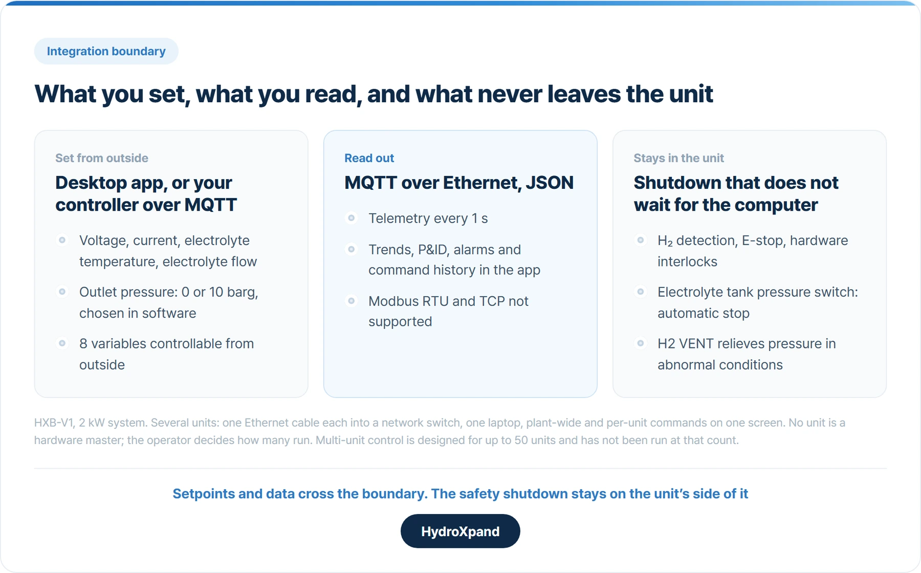
Four values are set directly: voltage, current, electrolyte temperature and electrolyte flow. In normal use the current is held constant and the other conditions are set around it. Outlet pressure is chosen in the same application, 0 or 10 barg, and can still be changed after delivery. It is not a hardware option fixed at the factory.
Telemetry runs at one-second intervals. The application shows trends on a Dashboard, takes setpoints on a P&ID screen, keeps alarms and command history, and runs automated sequences such as ramp-and-hold tests.
The record matters later rather than now. Whether cell voltage creeps up at the same current, or whether the electrolyte left its target temperature for a while, is what tells you when servicing is due and why.
Several units, one screen
One HXB-V1 makes 480 NL/h, about 1 kg a day. Above that, units are added.
Each unit takes one Ethernet cable into a network switch, and one cable runs from the switch to a laptop. The desktop application's multi-unit screen lists every connected unit with its status. A command to all units and control of a single unit are issued from the same screen.
Hydrogen outlets join one header, and the dryer and storage downstream are shared. Five units in a rack make a 10 kW class plant producing about 5 kg a day.
No unit is a hardware master. Each HXB-V1 is a complete generator and coordination is done in software. How many units run, and at what output, is the operator's decision.
The multi-unit software is designed for up to 50 units. We have not run that many at once, so a plant in the tens of units should be judged on operating evidence rather than the software limit. Beyond that, we design around our 30 kW stack.
Every unit is a complete generator. Taking one out for service leaves the rest running.
Connecting to your own control system
Where a site has an energy management system or a higher-level controller, that system should read and write the unit, not the desktop application.
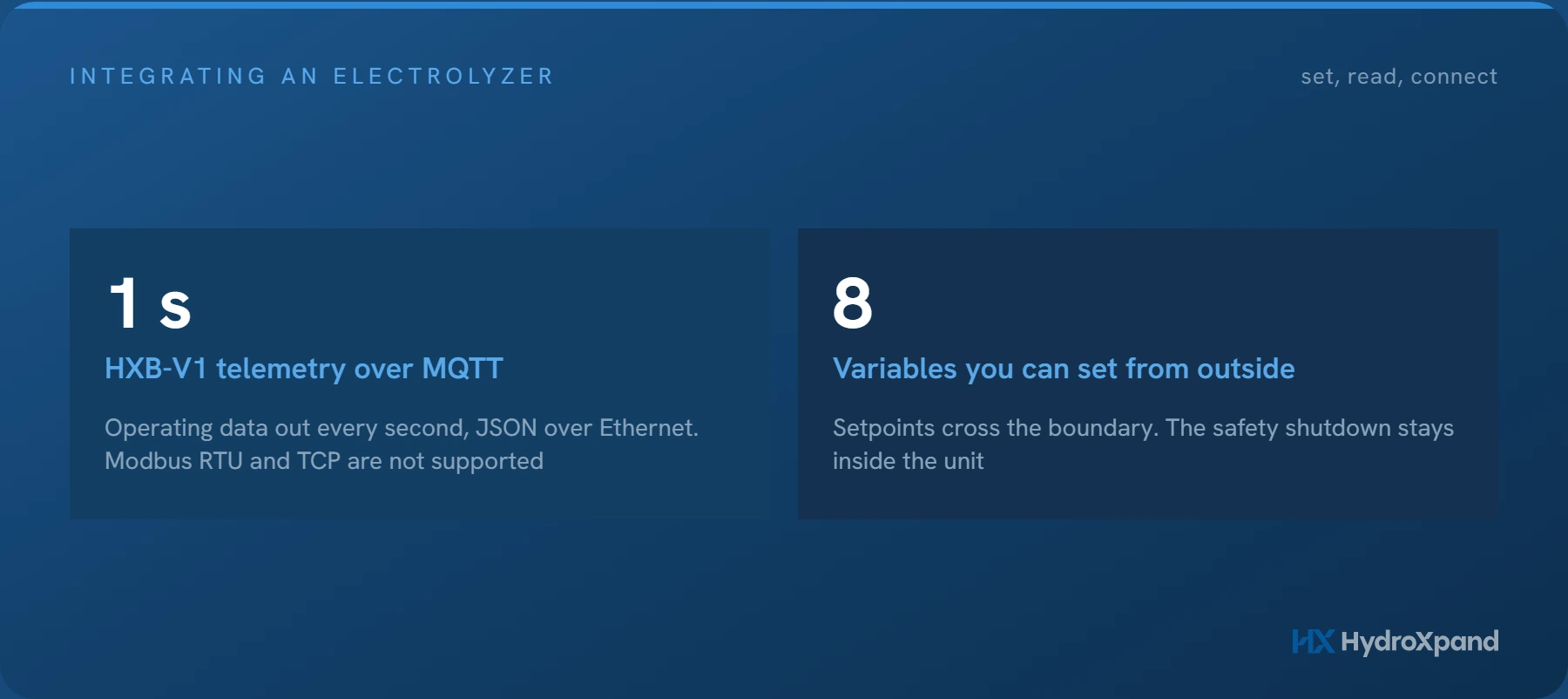
The interface is MQTT over Ethernet. Operating data and control commands are exchanged as JSON, and eight variables can be controlled from outside.
The connection is defined with your system's engineer at the design stage: which values are published and how often, which commands the unit accepts, which side handles each safety interlock, and where the integration logic lives.
Modbus is not supported, neither RTU nor TCP. A protocol mismatch found after delivery means adding a gateway or changing the upper system. Found during review, it costs a conversation.
If your controller only speaks Modbus, settle how the unit will connect before you order it.
SourcesMQTT, the OASIS standard messaging protocol for IoT · Modbus Organization
Remote access is not unattended operation
Remote access to the computer running the desktop application gives monitoring and control from off site. It is access to that computer, not a cloud service in the unit. Feed water is topped up by the internal pump, so nobody visits to refill it.
One practical detail: the computer's Ethernet port becomes dedicated to the unit, so a computer that also needs remote access needs a second port, such as a USB Ethernet adapter.
Whether a hydrogen installation may run with nobody present is a separate question. It depends on the site risk assessment, ventilation and the regulations that apply, and it is decided by whoever operates the site, not by the equipment supplier.
What supports that decision is the shutdown inside the unit. Hydrogen detection, an emergency stop and hardware interlocks are standard, and a pressure switch on the electrolyte tank stops the system automatically. In abnormal conditions pressure is relieved through the H2 VENT line. These sit in the unit itself, so they stay with it however far away the computer is.
Buying the stack alone: the control is yours
A system and a stack from the same supplier start from different places.
With HXB-V1 the control, instrumentation and safety logic are inside, and the application and MQTT interface come with it.
Our 2 kW stack, HXS-2, has no onboard PLC and no standard communication interface. Flow, pressure on both sides, current and voltage, temperature, leakage and emergency stop belong to an external controller, which also commands the pump and power supply. What to measure where is set out in the public HXS-2 stack integration guide.
| HXB-V1 system | HXS-2 stack alone | |
|---|---|---|
| Setpoints | Desktop appvoltage, current, temperature, flow | Your controller |
| Outlet pressure | 0 or 10 barg in software | Your pressure control10 barg is the H₂-side maximum |
| Data out | 1 s telemetryMQTT over Ethernet, JSON | Your instrumentation |
| Safety | H₂ detection, E-stop, interlocksbuilt in | Detection, interlocks, E-stopin the system you build |
| Starting point | Integration items agreed with us | Stack integration guide |
Four things to check, whoever the supplier is
- The variables that can be read and written from outside, split into read-only and writable, item by item, with the recording interval.
- The communication standard: physical layer, protocol and data format, set side by side with your own. Asking what is not supported is the quickest way in.
- Who coordinates several units. A hardware master and independent units coordinated in software behave differently when one unit is taken out.
- The shutdown path. Whether a stop signal passes through software or acts in hardware on its own, and how the unit accepts a stop command from your system.
A supplier that answers those four item by item has given you enough to start a design. Ours are on the product page; the integration logic is agreed against your system.
- What is an electrolyzer stack→What a stack is made of, how cell count scales output, and what decides performance.
- Between one and fifteen kilograms a day→How many units to install, and where repeating the 2 kW unit stops.
- What turnkey includes in a 2 kW electrolyzer→What one unit contains before it is connected to anything.
- Running an electrolyzer on solar→Why a writable setpoint is not the same as following a swinging supply.
- HXS-2 durability data→HXS-2 at constant current: how voltage rise is read from a long log.
- HXB-V1 handbook · Operation and control→The application screens, setpoints and protocols in detail.
- HXS-2 stack integration guide→Instrumentation by location, loop diagram, ports and heat load.
- HXB-V1 · 2 kW system→The controls, telemetry and safety rows of the specification.
Frequently asked questions
Can the HXB-V1 connect to a Modbus control system?
No. Modbus RTU and TCP are not supported; the interface is MQTT over Ethernet with data exchanged as JSON, so the connection should be settled at the design stage.
How many units can be run from one screen?
The multi-unit software is designed for up to 50 units. That is a design limit rather than a count we have run at once, so large plants are judged on operating evidence.
Can the system run with nobody on site?
Remote access to the computer running the desktop application gives off-site monitoring and control. Whether it may run unattended depends on the site risk assessment, ventilation and applicable regulations, and is decided by the site operator.
Sources
- MQTT: The Standard for IoT Messaging — OASIS
- Modbus Organization — Modbus Organization
Looking at AEM for a specific application?