The order in which to work through an abnormal condition, plus causes and actions for four symptoms. Following it lets you capture the information that matters before shutting down, and then move on to checks that are safe to make.
For most symptoms the cause is not inside the stack but in electrolyte condition, flow or water make-up. Start there.
- FirstJudge the hazard · record · stop
- SymptomsFour
- Usual causeElectrolyte condition · flow · water make-up
First timeFollow the checklist from the top exactly as written. Of the four symptoms, read only the one you are seeing.
Done this beforeGo straight to the symptom sections. The last section lists what to gather before contacting us.
On this pageThe order to work in
The order to work in
- Judge the hazard level first.
- Record the as-found condition.
- If it is safe to observe for a moment, record before you change anything.
- Always capture stack current and voltage, and electrolyte flow and temperature.
- If you measure them, add hydrogen flow, pressure and purity, and oxygen purity.
- Write down what you saw and heard too: pump noise or cavitation, gurgling, an unstable wet return at the outlet, odd vent behaviour, visible leakage.
- Make it safe before touching anything.
- Ramp stack current to 0 A and stop electrolysis from the app.
- Set Power Control OFF before touching any electrical connection.
- Read the alarm entry.
- Open the relevant entry in Alarms & Events and copy the values as shown.
- Read the limit against the measured value first: it tells you which threshold was reached and by how much.
- If the log shows the system reduced load or stopped by itself, treat it as safety-related until the cause is known.
- Run the fast go / no-go checks.
- Vent and outlets: confirm H2 OUT, H2 VENT and O2 OUT are not blocked, kinked or covered, and that no downstream valve was closed by accident.
- Electrolyte circulation: kinked tubing, visible blockage, signs of trapped air such as bubbles or surging, abnormal pump behaviour. If flow was low or unstable, fix that first, because it quickly turns into abnormal temperature and voltage.
- Cooling: confirm the fans and heat-exchanger airflow paths are clear, and clean them if needed.
- Electrical: visual inspection only. Loose cables or connectors, discolouration or overheating marks, an unusual smell. Do not open enclosures unless qualified.
- Apply one corrective action at a time.
- Make one change and check whether it improves. If it does not, undo it and move to the next likely cause. Never change several settings or parts at once.
- Restart carefully, or ask us.
- If you restart, begin at low current and increase only after flow and temperatures are stable.
Alarms: meaning and action
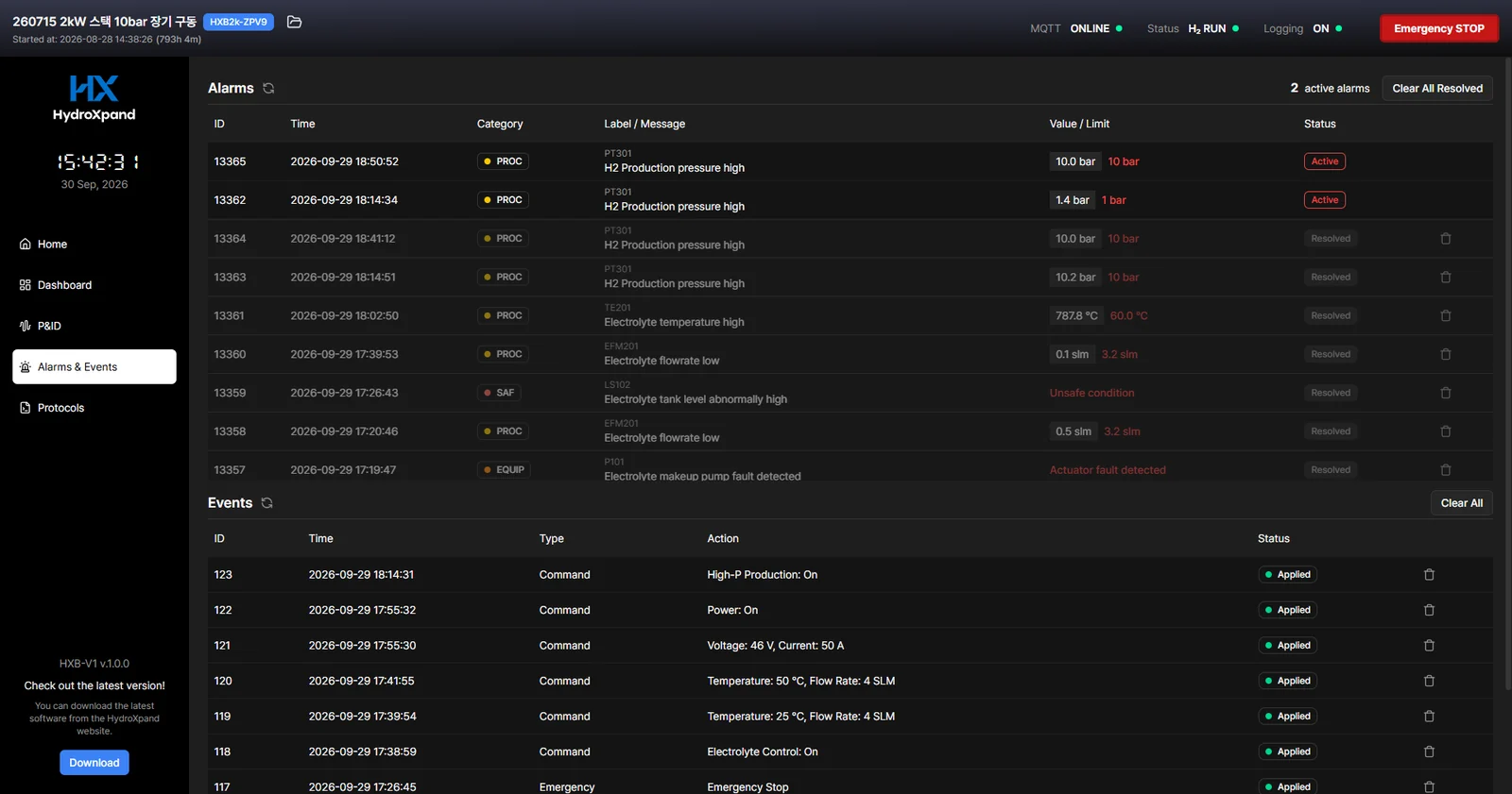
The English text below is the message exactly as the control app's alarm table shows it; wording can differ slightly between app versions. What the three levels mean is in the Alarms and events section of the Operation and control chapter. If the same alarm returns after you have acted, send us the alarm entry as it is.
Emergency stop
| App message | Label | Meaning | What to do |
|---|---|---|---|
| Hydrogen leak detected | HLS301 | Hydrogen was detected inside the unit. | Keep away and ventilate. Remove ignition sources nearby and follow the emergency response in the Safety chapter. Do not restart until the cause is found. |
| Electrolyte leak detected | ELS201 | Electrolyte was detected at the base of the unit. | Put on PPE, switch off, then find the leak. Deal with spilled electrolyte as the electrolyte section of the Safety chapter describes. If it leaks inside the enclosure, contact us. |
| Electrolyte tank pressure higher than 60 psi | PSH101 | Electrolyte tank pressure exceeded its limit. | Check that the O2 OUT line is not blocked, kinked or submerged at its end. Gas leaves the tank this way. |
| Electrolyte tank level abnormally high | LS102 | The tank filled up to the overfill switch. | Check whether too much electrolyte was filled or the make-up pump keeps running. Heavy foaming can also trip it. Drain the excess back to normal level, then clear the stop. |
| Electrolyte flow critically low (pump failure) | EFM201 | There is almost no circulation flow. The circulation pump has most likely stopped. | Check that the tubing is not blocked or kinked and the level is sufficient. If nothing is wrong and it recurs, contact us. See Symptom D. |
| H2 production pressure critical high | PT301 | Hydrogen pressure rose to a critical level. | A closed downstream valve or a blocked line is the likely cause. Confirm pressure has been relieved, then check from H2 OUT to the end of your line. See Symptom C. |
| H2 outlet pressure critical high | PT302 | ||
| DISCONNECTED | — | The link to the control app was lost for longer than allowed. It shows as a flashing red front LED rather than as an alarm entry. | Check the LAN cable and the PC. Set the PC so sleep or update restarts do not interrupt it, and restart the app. |
Fault stop
| App message | Label | Meaning | What to do |
|---|---|---|---|
| Electrolyte refill failure | LS101 | Water make-up has not succeeded for too long. | See When make-up starts to fail under Water make-up in the Operation and control chapter. |
| Electrolyte circulation lost | EFM201 | Electrolyte circulation flow stayed far below the setpoint. | Look for kinked tubing, trapped air or a pump problem. See Symptom D. |
| Electrolyte tank temperature high (stop) | TE101 | Electrolyte temperature stayed far above the setpoint. | Check that fan and heat-exchanger airflow is not blocked, the ambient temperature is within the installation limits and circulation flow is normal. Let it cool, remove the cause, then start. |
| Stack inlet temperature high (stop) | TE201 | ||
| Stack outlet temperature high (stop) | TE202 | ||
| Unsafe operating temperature | TE101/ | A temperature that cannot occur in normal operation, at freezing or boiling level. | If it may have frozen, do not operate; contact us. In any other case, contact us too. |
| Temperature sensor fail | TE | A sensor reading went outside its measurable range. The sensor or its wiring has failed. | Send us the alarm entry as it is and contact us. Do not open the enclosure. |
| Current sensor fail | CT201 | ||
| Voltage sensor fail | PSU48 | ||
| Pressure sensor fail | PT301/ | ||
| Makeup pump fault | P101 | The make-up pump was commanded on but draws no current. | Contact us. Without make-up the level soon falls. |
| Circulation pump fault | P201 | The circulation pump was commanded on but draws no current. | Contact us. Running current without circulation damages the stack. |
| Hydrogen solenoid valve 1 / 2 falt detected | GSV301/ | A valve was commanded on but draws no current. | Contact us. These valves serve pressurised operation and the emergency vent. |
| Solenoid valve 3 fault | GSV303 | ||
| Magnetic contactor falt detected | MC401 | The stack power contactor does not close as commanded. | Contact us. |
Warning
| App message | Label | Meaning | What to do |
|---|---|---|---|
| Electrolyte tank temperature high · Electrolyte temperature high | TE101TE201TE202 | Electrolyte temperature is starting to rise above the setpoint. | Check cooling airflow and ambient temperature. If it keeps rising, it becomes a fault stop. |
| Electrolyte flowrate low | EFM201 | Circulation flow is below the setpoint. | Look for kinked tubing and trapped air. If it persists, see Symptom D. |
| H2 Production pressure high | PT301 | Hydrogen pressure is above the normal range. | Check for back pressure downstream. See Do not create back pressure in the Downstream chapter. |
| H2 Outlet pressure high | PT302 | ||
| Electrolyte cooling fan fault detected | F201 | A fan was commanded on but is not turning. | Check for debris or blockage around the fan. Left alone it leads to overheating. If it persists, contact us. |
| Axial fan fault detected | F401 | ||
| Cartridge heater falt detected | CH101 | The heater was commanded on but draws no current. | Warm-up will not happen or will be slow. Contact us. |
Symptom A. Stack voltage rises quickly or sits unusually high
- Electrolyte temperature too low
- Check the electrolyte temperature and its setpoint in the app. If there is no upward trend toward the setpoint, or the heater status looks abnormal, stop operating and contact us.
- Electrolyte concentration too low
- Confirm the electrolyte is 0.1 M KOH and review the recent water make-up history. If dilution is suspected, stop and replace it with fresh 0.1 M KOH. Restart at low current, confirm the voltage trend is stable, then ramp up. If it is still abnormal with fresh electrolyte, contact us.
- Internal crossover or membrane damage suspected
- Stop operating. Keep the electrolyte level trend, the make-up events and the stack current and voltage as evidence, and contact us.
- Electrolyte flow insufficient or unstable
- Check the flow indication and any related alarms in the app. If the pump is on but there is no flow, if it does not start reliably, or if its behaviour is abnormal, stop operating and contact us.
- Current drops although no setting was changed
- When stack voltage reaches the power supply's voltage limit, the supply lowers the current by itself. In that case the voltage of a single cell inside the stack has often risen sharply. The control app shows only total stack voltage, so on screen the voltage sits at the limit while the current falls. In our tests a slow rise of stack voltage at the same current appeared first, 10–24 hours before the stop. Stop operating and do not restart repeatedly. Keep the current and voltage trends and contact us.
Symptom B. Stack voltage falls quickly or sits unusually low
- Electrolyte temperature too high
- Check the electrolyte temperature and its setpoint in the app. If it does not come down toward the expected range, or cooling-related status looks abnormal, stop operating and contact us.
- Electrolyte concentration too high
- Check the electrolyte level and confirm water make-up is working. Bring the electrolyte back to the 0.1 M KOH specification following your site procedure. Restart at low current, confirm the voltage trend is stable, then ramp up.
- Electrolyte flow insufficient or unstable
- Check the electrolyte level, confirm make-up is enabled and active, and see whether the level rises as expected. If make-up appears to run but the level does not recover, the DI water source is empty or not supplying. If refilling does not raise the level, stop operating and contact us.
- Membrane damage in the stack
- If voltage is still unusually low after temperature, concentration and flow are restored, stop operating. Keep the stack current and voltage trend, electrolyte temperature and flow, and recent service history as evidence, and contact us.
Symptom C. Pressure is not as expected or is unstable
- Solenoid valve malfunction suspected
- Confirm which pressure mode is selected in the app, 0 barg or 10 barg. Switch the mode and watch whether the pressure responds accordingly. If the mode changes in the app but pressure does not respond, becomes unstable, or cannot reach 10 barg, stop operating and contact us.
- Relief valve malfunction suspected
- If pressure cannot build to 10 barg, or drops quickly during pressurised operation, relief valve leakage may be the cause. Stop operating and contact us.
- Pressure sensor malfunction suspected
- If the reading jumps suddenly, sticks at one value, or is simply implausible, suspect the sensor. Stop operating and contact us.
- Hydrogen outlet path blocked
- The moisture that leaves with the hydrogen carries alkaline residue, which can build up as deposits in valve orifices and narrow tubing as it dries. Suspect this if hydrogen pressure creeps up or fluctuates although no setting was changed. Stop operating, depressurise, then check the tubing and valves from H2 OUT to the end of your downstream line. Do not dismantle valves inside the unit yourself; contact us.
- Membrane damage in the stack
- If pressure stays unstable or cannot be held in 10 barg mode while temperature and flow behave normally, suspect an internal stack issue. Stop operating and do not keep restarting. Keep the pressure trend, the current and voltage trend and the relevant alarm entry as evidence, and contact us.
Symptom D. Electrolyte flow is low or unstable
- Electrolyte level too low
- There is not enough liquid for stable circulation. Check the level in the app and confirm make-up is working and DI water is available. If the level does not recover as expected, stop operating and contact us.
- Circulation pump malfunction suspected
- Check the flow indication and any related alarms in the app. If the pump is on but there is no flow, flow is unstable, or its behaviour is abnormal, stop operating and contact us.
- Make-up takes longer than usual or the level recovers slowly
- The make-up pump is not drawing water properly. Check that the DI water reservoir is not empty, the H2O IN hose is submerged, the reservoir is not too far below the unit, and the hose is not full of air. Left alone, make-up stops and circulation flow falls. Keep electrolysis stopped while you find the cause.
- Membrane damage in the stack
- If flow stays unstable or cannot be held, suspect an internal stack issue. Stop operating and do not keep restarting. Keep the pressure trend, the current and voltage trend and the relevant alarm entry as evidence, and contact us.
Contacting support
When to ask us
- Stack voltage behaviour stays abnormal after you have checked and corrected level and condition, flow and temperature.
- The same problem recurs under normal operating conditions and the symptom guide above does not resolve it.
- You are planning non-standard operation and want the safe limits and recommended practice confirmed.
- A high-severity alarm persists or returns after the basic checks.
- You see behaviour the symptom guide does not explain, such as erratic readings or unexplained mode changes.
Send these and diagnosis is faster
- The full alarm entry: time, category, label, message, measured value against the limit, and status.
- The stack current and voltage and the electrolyte flow and temperature trends across the abnormal period.
- The electrolyte specification and the date it was last replaced.
- Any recent change: a new stack, new electrolyte, piping modification, a replaced component.
- Accumulated run hours and the number of start-stop cycles.
What this chapter is based on
- HXB-V1 datasheetPDF · 2.1 MB
- HXB-V1 outline drawingPDF · 1.9 MB
- HXB-V1 user manualOn request
Ask the engineer who built it
If your case is not covered here, send us the operating condition and what you observed. The engineer who designed the system answers directly.