How to run a commissioned system day to day: what the six front-panel LED states mean, the start-up and shutdown sequences, recommended setpoints and operating ranges, water make-up, and how to read alarms.
- Recommended point50 A · 50 °C · 4 L/min
- Water useAbout 0.55 L/h
- LED statesSix
First timeRead just two sections first: the front-panel LED states and daily start-up. Those two are enough to run the system every day; the rest is reference for when you need it.
Done this beforeGo straight to the recommended setpoints and to water make-up. The section on operating points not being reached covers the constraints when using this as an evaluation station.
On this pageThe control app
The control app
The system is operated from a desktop app. The tabs run left to right in working order, and the actual controls live on the P&ID tab.
- Home
- Session summary and safety snapshot
- Dashboard
- Trends and KPIs for stability and performance
- P&ID
- The main control page: apply setpoints and operate
- Alarms & Events
- Alarms, events and command history
- Protocols
- Automated sequences for repeatable tests
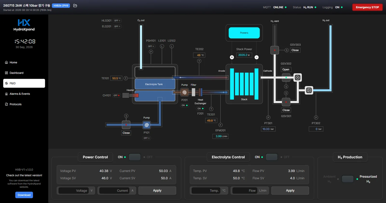
Top bar
- MQTT
- Whether the app is connected to the system
- Status
- Whether the system is running or stopped
- Logging
- Logging state
- Emergency STOP
- Immediate shutdown
Front-panel LED states
A single front-panel LED shows the system state. Six states are distinguished by colour and blinking.
| State | Colour | Meaning | Action |
|---|---|---|---|
| EMERGENCY | Red, solid | Emergency stop is active and operation has stopped | Remove the cause, press the red Reset button on the front panel or Emergency STOP in the app once to release, then restart in the normal order |
| DISCONNECTED | Red, blinking | The link to the control app on the PC is lost | Check the Ethernet link and launch the app. If the LED does not return to yellow, press the red Reset button or Emergency STOP once to release |
| STANDBY | Yellow | Idle, no hydrogen production | Normal idle state |
| EL_CTRL | Blue | Electrolyte control on, power control off, no hydrogen | Warm-up, cool-down or circulation |
| PWR_CTRL | Purple | Stack power is on while electrolyte control is off | Not a recommended state. Turn Power Control off and return to the normal sequence |
| H2 RUN | Green | Normal hydrogen production | Normal operation; keep watching the app |
The recommended flow is STANDBY, then EL_CTRL, then H2 RUN.
Daily start-up
Before you start
- The LED shows STANDBY, or the system is safely stopped.
- There are no critical alarms in Alarms & Events.
- Electrolyte level is in the normal range.
- The H2O IN line is submerged in the DI water reservoir.
- H2 OUT, O2 OUT and H2 VENT all run to safe discharge points and are unobstructed.
- There is enough DI water for the run you have planned.
Sequence
- Confirm the safety snapshot on Home is normal.
- Check on the Dashboard that temperature, current and voltage trends look plausible.
- P&ID, Electrolyte Control
- Set the temperature and flow targets and click Apply.
- Turn Electrolyte Control ON.
- Confirm the LED changes to EL_CTRL.
- P&ID, Power Control
- Set the voltage and current targets and click Apply.
- Turn Power Control ON.
- Confirm the LED changes to H2 RUN.
- In Alarms & Events, confirm no alarm appeared during ramp-up and that your commands were logged.
Recommended setpoints and operating ranges
| Parameter | Recommended | Operating range |
|---|---|---|
| Stack current | 50 A | 15–67 A |
| Stack voltage | 40 V | 24–48 V |
| Electrolyte temperature | 50 °C | RT–70 °C |
| Electrolyte flow | 4 L/min | 2–5 L/min |
| Hydrogen pressure | 0 barg | 0 or 10 barg |
When the operating point you set is not reached
Running galvanostatically inside the rated window is not a concern. Both a voltage setpoint and a current setpoint are applied together, however, and the combination is constrained, so in the tests below the operating point you request may not be delivered as entered.
- IV-curve measurement, where the operating voltage sweeps over a wide range
- Low-current evaluation of a short stack or a third-party stack
- Operation below or above the recommended current window
If you plan to use the HXB-V1 as an evaluation station, send us your target operating points and test plan. Our engineer will come back with what is achievable and how to set it.
What to watch during operation
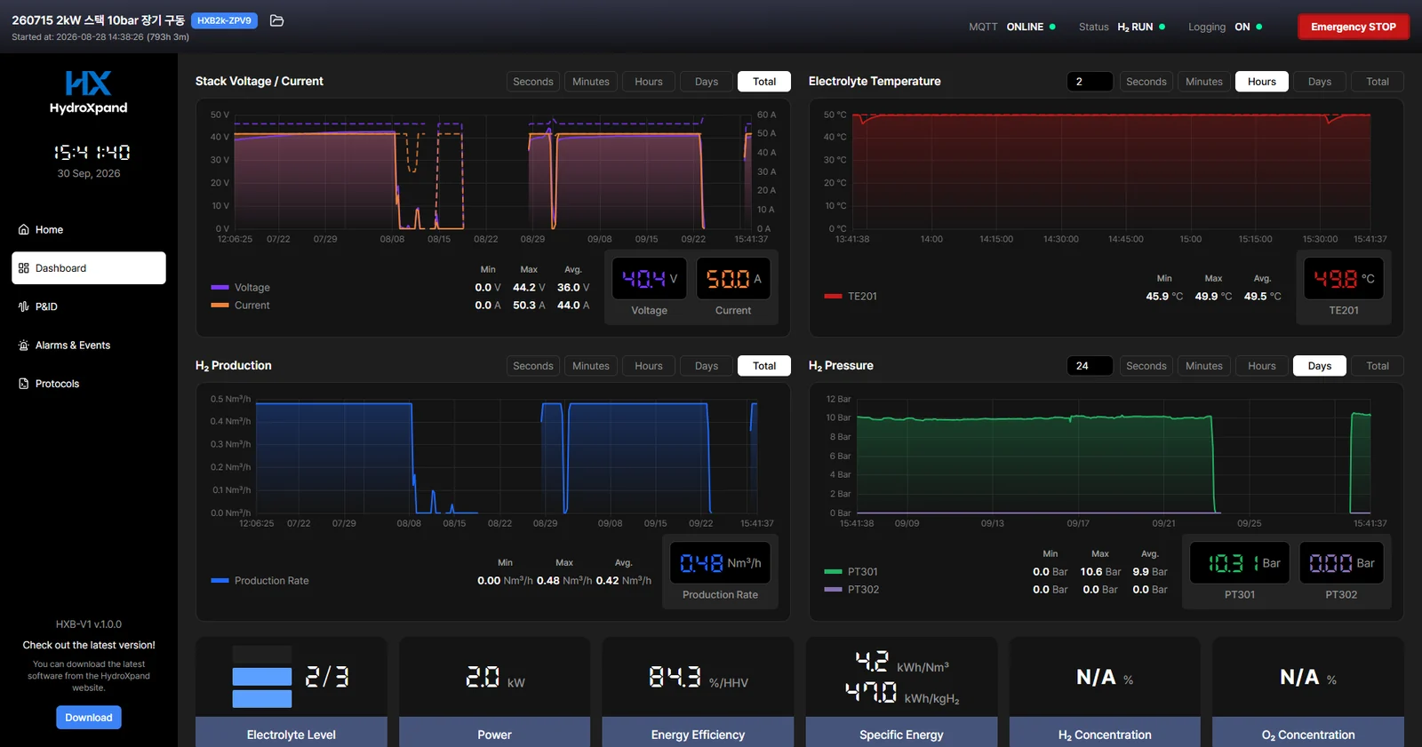
- Stack voltage and current
- Confirm they respond to your targets and stay steady. If voltage jumps or swings widely at constant current, stop and investigate.
- Electrolyte level
- It must stay in the normal range. If it trends down or becomes unstable, stop and correct the make-up condition.
- Electrolyte flow
- It must stay stable near the setpoint. Temperature control and safe operation both depend on it.
- Electrolyte temperature
- It should move toward the setpoint and settle. If it keeps rising despite circulation and cooling, stop and investigate.
- Alarms
- Do not ignore a recurring alarm. Investigate it immediately.
Water make-up
Water is consumed during operation, so make-up is needed to hold both level and concentration. Keep the H2O IN line submerged in the DI water reservoir and the system tops itself up.
Measured make-up
From our own tests on a 23-cell 2 kW stack at 50 A and 60 °C.
- Theoretical consumption
- About 0.39 L/h at 50 A
- Measured consumption
- About 0.53–0.55 L/h at 50 A
- Why measured exceeds theory
- Water evaporates and leaves with the product gas. Moisture exits through both the hydrogen and the oxygen outlet.
- Make-up interval
- Under the same conditions it typically triggers about every 1.5 hours
- Sizing the reservoir
- Unless your own measurements say otherwise, plan on 0.5–0.6 L/h. Never let the reservoir run dry during operation.
Reading the level indicator
- The tank graphic in the control app has three bars. One to three bars is normal.
- When the level switch (LS 101) senses low level the make-up pump runs, and it stops when the upper level is reached. The level moving between one and three bars is normal.
- A separate overfill switch (LS 102) sits above that. If it trips, the unit goes to emergency stop. This means too much electrolyte was filled or water keeps flowing in.
- If make-up keeps failing, the unit goes to fault stop. An empty DI water reservoir will eventually stop operation.
When make-up starts to fail
Make-up usually degrades before it stops. In our long-run tests the time taken by a single make-up grew to several times normal before make-up stopped altogether. Check the path as soon as you see the signs below.
- A single make-up takes longer than usual.
- The level indicator stays at one bar for longer.
- The make-up interval changes although the operating conditions are the same.
- Reservoir empty
- Refill with DI water. Size the reservoir for the intended run time.
- Suction hose not submerged
- Make sure the end of the H2O IN hose sits submerged near the bottom of the reservoir and is not kinked or crushed.
- Reservoir too far below the unit
- The higher the make-up pump has to lift water, the more likely it is to fail to draw. Keep the reservoir at about the same height as the unit.
- Air in the hose
- A long run of air in the hose breaks suction. Fill the hose with water and reconnect it.
Normal shutdown
- Stop electrolysis.
- Turn Power Control OFF on the P&ID.
- Confirm current drops to 0 A and the LED changes from H2 RUN to EL_CTRL.
- Cool the stack and electrolyte.
- Keep Electrolyte Control ON for a while. The LED stays at EL_CTRL.
- Stop circulation.
- Turn Electrolyte Control OFF and confirm the LED changes to STANDBY.
- After shutdown
- Confirm no alarm is still active in Alarms & Events.
- Visually check the front-panel ports and external tubing and fittings for leaks.
Alarms and events
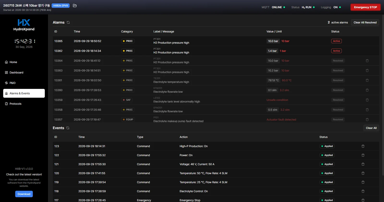
The Alarms & Events page holds two tables. Alarms are abnormal conditions that need attention; Events are the history of commands and actions. Use Clear All only after the underlying condition is resolved.
Three alarm levels
Alarms fall into three levels according to what the unit does. When an alarm appears, first see which level it is. The way back to operation differs by level.
| Level | What the unit does | To resume | Typical causes |
|---|---|---|---|
| Warning | Shows and logs the alarm. Operation continues. | No need to stop, but check the cause. If the same warning keeps returning, contact us. | Temperature or flow starting to drift from the setpoint; fan, pump or heater not responding as commanded |
| Fault stop | Switches off stack power first, then electrolyte control a few seconds later, and goes to STANDBY. It only triggers while electrolyte control is on. | Remove the cause, then start again from STANDBY in the normal sequence. | Water make-up failure, loss of circulation flow, overtemperature, sensor failure, valve or contactor fault |
| Emergency stop | The unit itself switches every control off at once and opens the H2 VENT valve. The LED turns solid red. | Remove the cause, then press the red Reset button on the front panel or Emergency STOP in the app once. It does not clear by itself when the cause goes away. | Hydrogen leak detected, electrolyte leak detected, tank overpressure, tank overfill, hydrogen overpressure, loss of connection to the control app |
Releasing an emergency stop
- Confirm yourself that the cause is gone.
- Once released, the unit does not trip again even if the cause is still there. Check before you release.
- Press either the red Reset button on the front panel or the Emergency STOP button in the control app, once.
- Reset restarts the controller into standby. It takes a few seconds.
- Press Emergency STOP in the app only once. Pressing it again after release puts the unit back into emergency stop.
- Check that the front LED has turned yellow (STANDBY).
- Start again in the normal order.
- After release, electrolyte control and power control are both off. Switch on electrolyte control first, and power control only once circulation and temperature are stable.
- Use Clear All only for alarms whose cause has been resolved.
Category column
Depending on the app version, the category column of the alarm table shows one of the four below. The category tells you where the alarm came from. Use the three levels above to judge what the unit did.
- SAF
- Safety-related condition
- PROC
- Process condition
- EQUIP
- Equipment or actuator abnormality
- COMM
- Communication or network issue
Fields on an alarm
An identifier, the time it was raised, the category, a short label, a message, the measured value against the limit, and the current status. Sending these to us verbatim speeds up diagnosis.
Reading the label
The label is the tag of the sensor or part that raised the alarm. It matches the same tag on the P&ID screen of the control app. Some tags are absent on some unit versions.
| Label | What it is |
|---|---|
| TE 101 | Electrolyte tank temperature |
| TE 201 · TE 202 | Electrolyte temperature at stack inlet · outlet |
| LS 101 | Tank level switch. Starts and stops water make-up |
| LS 102 | Tank overfill switch |
| PSH 101 | Tank pressure switch |
| EFM 201 | Electrolyte flow meter |
| P 101 | Water make-up pump |
| P 201 | Electrolyte circulation pump |
| CH 101 | Electrolyte heater |
| F 201 · F 401 | Cooling fan · axial fan |
| PT 301 · PT 302 | Hydrogen production pressure · hydrogen outlet pressure |
| GSV 301 – 303 | Hydrogen solenoid valves. 303 is the vent valve opened on emergency |
| HLS 301 | Hydrogen leak sensor |
| ELS 201 | Electrolyte leak sensor |
| CT 201 | Stack current measurement |
| MC 401 | Stack power contactor |
PLC and SCADA integration (Modbus TCP)
The unit supports Modbus TCP over Ethernet. A PLC or SCADA system can read operating data without the control app and, once it takes control, write setpoints and run commands too. Ask us for the latest register map.
- Role
- Modbus TCP server (slave)
- Address
- The unit's LAN port · 192.168.121.2 · port 502 · Unit ID 1 (units shipped as a multi-unit set use the address list supplied with them)
- Concurrent connections
- Up to 5
- Update rate
- Measurements update once per second. Poll at 1 s intervals.
- What you can read
- Operating state, interlock and emergency-stop status, measurements such as temperature, pressure, flow, current and voltage, and the active setpoints
- What you can write
- Stack voltage and current, electrolyte temperature and flow setpoints, and run commands. Applied only after control has been handed over.
Monitoring only
Nothing to configure. Connect and read. Writes are not applied until control has been handed over.
Integrating with a PLC
Once the unit is integrated with your PLC, the control app is not used. The unit has one LAN port, and the PLC takes it.
- Still works
- Alarm evaluation and warnings, fault stop and emergency stop. The unit's firmware evaluates and executes all of them, so they behave the same without the control app.
- Your PLC or SCADA must do
- Display and data logging. The control app's csv logging is no longer there, so record the values you need in your SCADA. We need those records to diagnose any issue.
- Connection supervision
- Instead of the link check with the control app, the Modbus watchdog supervises the connection to the PLC.
Handing over control
- As shipped, the control app holds control. For a PLC to control the unit, hand control to the PLC at commissioning and save that setting on the unit. The register map explains how.
- Control can only be taken with the watchdog enabled. If the PLC stops signalling within the set time, the unit releases every run command, stops operating and gives up PLC control. Once the PLC takes control again, operation can resume.
- When the watchdog expires the unit gives up PLC control without notice, and so does a restart if the control setting was not saved. Have the PLC confirm on every cycle that it still holds control.
- A rejected write does not return an error response. Always read back after writing to confirm the value was applied.
Protocols and data logging
Protocols
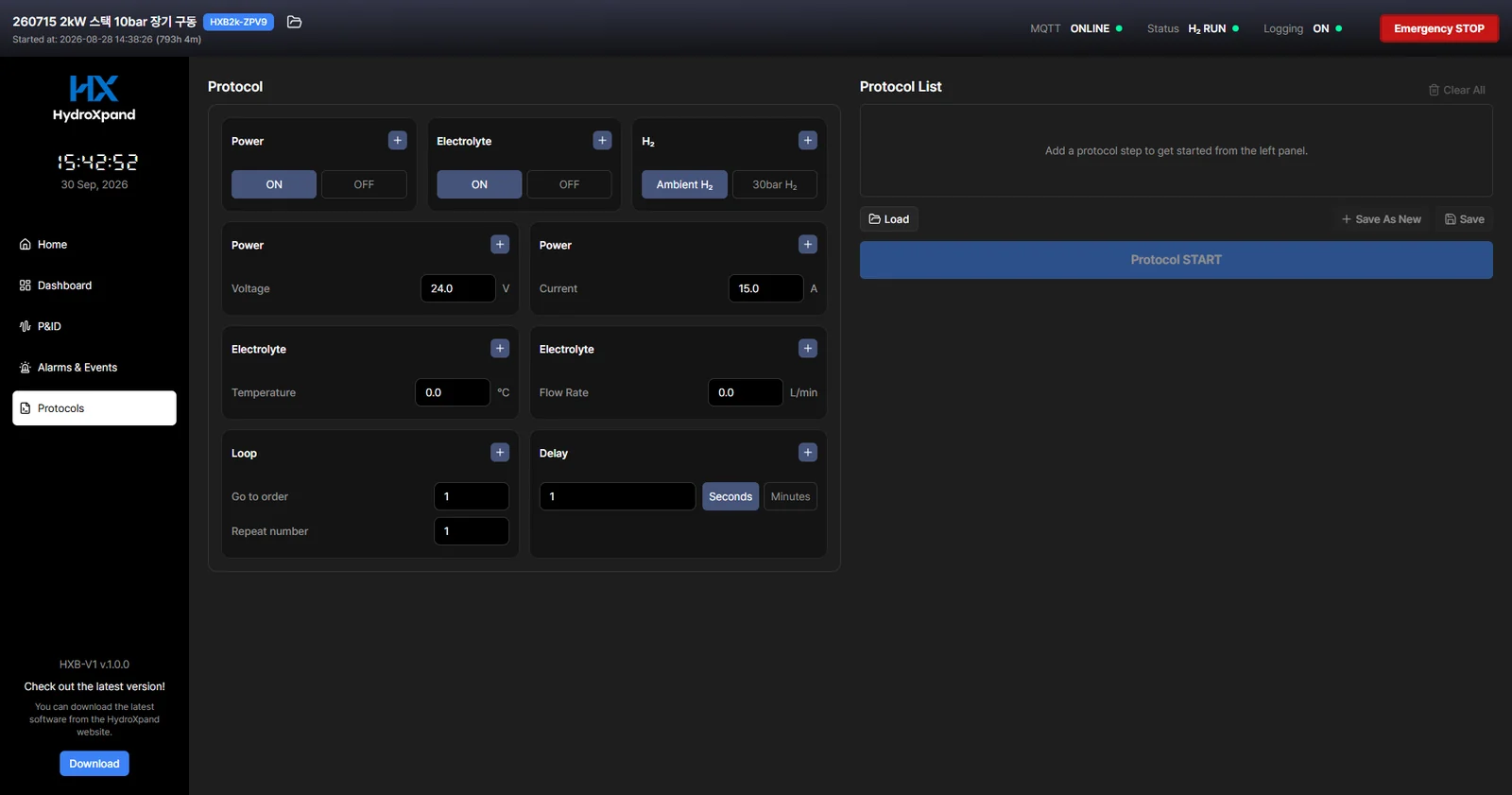
Used for repeatable sequences such as ramp-and-hold tests and long runs. A protocol is an ordered list executed top to bottom, and its steps can switch electrolyte control and power control on or off, apply setpoints, wait, and loop a section.
Automatic logging and export
- While the PC is connected and Logging is ON, operating data is recorded continuously.
- Use Project Manager to organise runs and to export the records.
- Select the project, then export from the project options menu; the file comes out as csv.
What this chapter is based on
- HXB-V1 datasheetPDF · 2.1 MB
- HXB-V1 outline drawingPDF · 1.9 MB
- HXB-V1 user manualOn request
Ask the engineer who built it
If your case is not covered here, send us the operating condition and what you observed. The engineer who designed the system answers directly.