What the HXB-V1 is for, how it looks and what flows inside, its specifications and electrical ratings, and the terms used in this handbook. Read it once before installation and come back when you need a value.
On this pageIntended use
Intended use#
The HXB-V1 is a 2 kW AEM water electrolysis system that makes hydrogen from DI water with a 0.1 M KOH electrolyte. One 6U 19-inch rack holds the stack (HXS-2), electrolyte tank, pumps, heat exchanger, power and controls.
- Laboratory research on AEM stacks, electrodes and operating strategies
- Small-scale hydrogen production and system-integration test beds
Installation, operation and maintenance are for people who know hydrogen safety and venting, high-current DC and alkaline electrolyte handling. If you modify the unit or run it outside the recommended conditions, verifying safety and performance is your responsibility and the warranty may change (see Warranty and service).
Product views#
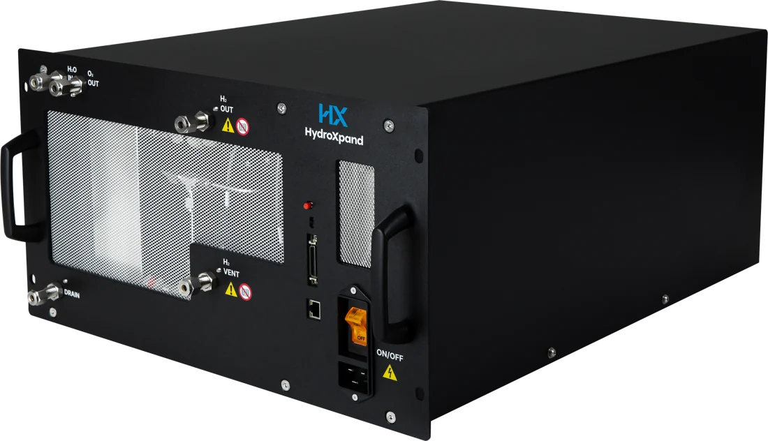
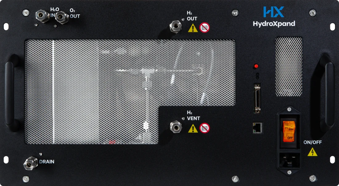

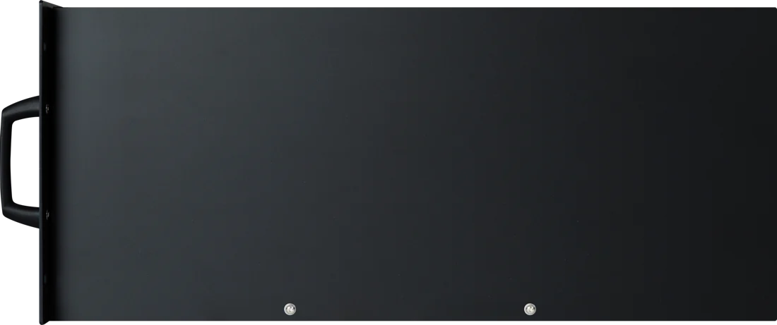
Flow inside the unit#
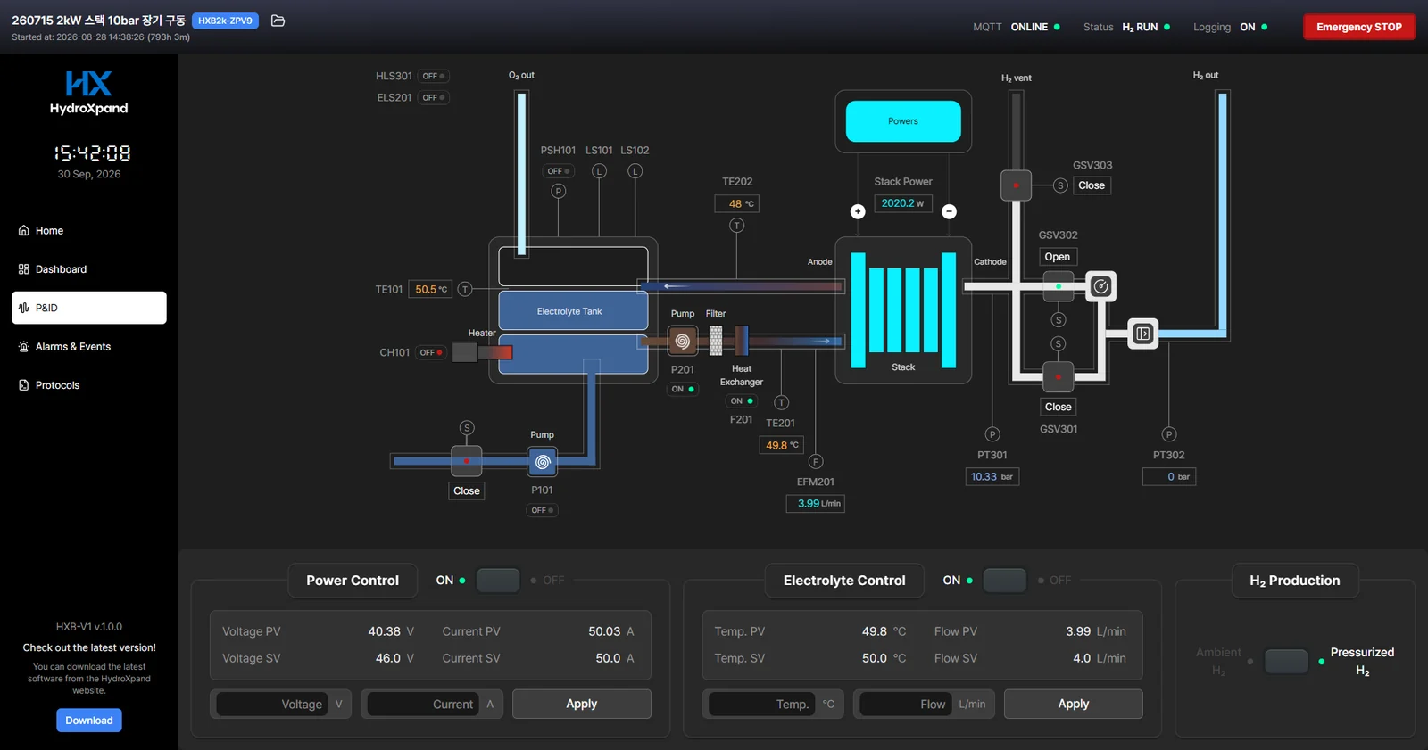
Electrolyte leaves the tank through the circulation pump and heat exchanger into the stack; oxygen and electrolyte return to the tank, where they separate. Hydrogen leaves the stack on its own line to H2 OUT. The make-up pump replaces the water used, through H2O IN.
Specifications#
The specifications below are the same values as the product page and datasheet. They are beginning-of-life values unless stated otherwise.
Production performance
- H₂ production
- 500 L/h (approx. 1 kg/day)
- Energy use (kW)
- 2.4 kW (BOL · 2.0 stack + 0.4 BoP)
- Energy use (kWh/Nm³)
- 4.8 (BOL)
- Energy use (kWh/kg-H₂)
- Stack 44 · system 54 (the difference, about 10 kWh/kg, is the BoP)
- Operating current
- 15–67 A (50 A recommended)
Hydrogen purity & pressure
- H₂ purity @ 0 barg
- 98–99% (no dryer) · ≥ 99.999% (with dryer)
- H₂ purity @ 10 barg
- 99% (no dryer) · ≥ 99.999% (with dryer)
- H₂ pressure
- 0 or 10 barg · chosen at order (relief valve); 35 barg by agreement
Power & water
- Power supply
- 200–240 V AC · 50/60 Hz · single phase
- Water conductivity
- Recommended ASTM D1193 Type II (≤1.0 µS/cm) · in-service ≤30 µS/cm
- Water consumption
- 0.55 L/h (50 A · 60 °C)
- Feed water top-up
- Built-in gear pump refills automatically
- Electrolyte
- KOH 0.1–1 M · circulation 2–5 L/min
Installation
- Ambient temp
- 5–45 °C
- IP rating
- IP 20
- Dimensions
- 482 × 647 × 266 mm (6U)
- Weight
- 51.3 kg
- Fluid connections
- H₂O · H₂ · O₂ · VENT · DRAIN 1/4″ double-ferrule
- Power inlet
- C20 AC inlet (C19 cable)
- Installation clearance
- Front ≥ 300 mm · rear ≥ 400 mm
Controls & communications
- Control
- Desktop app (MQTT/Ethernet)
- Direct control
- Voltage · current · electrolyte temperature · electrolyte flow
- Stack handling
- Removable · disassemblable · replaceable
- Telemetry
- 1 s interval · 8 external control variables · Modbus TCP supported (not RTU)
Safety & warranty
- Safety
- H₂ detection · emergency stop (control app) · interlocks · electrolyte tank pressure switch auto-stop
- Warranty
- 12 months from shipment, or from acceptance where an acceptance procedure applies (consumables excluded)
Electrical ratings and environment#
- Rated supply
- 200–240 V AC · 50/60 Hz · single phase · 2.4 kW
- Power connection
- IEC 60320 C20 inlet (16 A) · C19 power cord
- Protection class
- Class I. Plug into an earthed outlet.
- Enclosure rating
- IP20
- Location
- Indoor use only, non-condensing
- Ambient temperature
- 5–45 °C
- Altitude
- Up to 2,000 m
- Overvoltage category · pollution degree
- Overvoltage category II · pollution degree 2
- CE conformity
- Self-declared to the Low Voltage (2014/35/EU), EMC (2014/30/EU) and RoHS (2011/65/EU) directives, applying EN 61010-1, EN 61326-1 and EN IEC 63000. Download the declaration under “Sources for this chapter” below.
Labels on the unit#
 General warningBeside H2 OUT and H2 VENT, where hydrogen comes out. Follow the hydrogen section of the safety chapter.
 Do not obstruct the outletBeside H2 OUT and H2 VENT. Never block the outlets or stack things in front of them.
 Electric shock hazardBeside the power switch and C20 inlet. Always disconnect from the mains before opening any cover.
Terms#
| Term | Meaning |
|---|---|
| AEM | Anion exchange membrane: a membrane that passes hydroxide ions (OH⁻). |
| KOH | Potassium hydroxide, used as a 0.1 M solution for the electrolyte. |
| DI water | Deionised water. Quality is judged by conductivity (µS/cm at 25 °C). |
| MEA | Membrane electrode assembly: the electrodes and membrane that make up the heart of a cell. |
| BoP | Balance of plant: everything around the stack, such as power, pumps, tank, heat exchanger, piping, sensors and controls. |
| barg | Gauge pressure in bar, relative to atmosphere. |
| NL/h | Gas volume per hour in litres at standard conditions (0 °C, 1 atm). |
| BOL | Beginning of life. Specifications are BOL values unless stated otherwise. |
| SDS | Safety data sheet. Check it before handling KOH. |
| P&ID | Piping and instrumentation diagram. The P&ID screen in the control app shows the flow and measuring points inside the unit. |
| PSU | The power supply that feeds DC to the stack. |
Manufacturer#
- Manufacturer
- HydroXpand Inc.
- Address
- 3F, 59 Dongtansandan 6-gil, Hwaseong-si, Gyeonggi-do 18487, Republic of Korea
- Contact
- +82 70-4110-1201 · [email protected] · hydroxpand.com
Serial numbers take the form HXB-V1-YYMM-#### (year and month of manufacture, then a sequence number). Quote the serial number or Device ID from the label when you contact us.
What this chapter is based on
- HXB-V1 datasheetPDF · 2.9 MB
- HXB-V1 outline drawingPDF · 1.6 MB
- First start-up checklistPDF · 72 KB
- Routine check sheetPDF · 73 KB
- Maintenance logPDF · 48 KB
- Electrolyte logPDF · 73 KB
- HXB-V1 user manualPDF · 7.0 MB
- EU declaration of conformity (CE)PDF · 122 KB
Thank you. We read every answer.
Tell us what was missing and we will fix this page. Tell us what was missing →
Ask the engineer who built it
If your case is not covered here, send us the operating condition and what you observed. The engineer who designed the system answers directly.