Coupling an electrolyzer to a solar array is usually discussed as a question of response speed. The harder question is the floor: how far the load can drop before something other than efficiency stops you. On our own stack that limit is gas crossover, and we have 49 measured points that show where it sits.
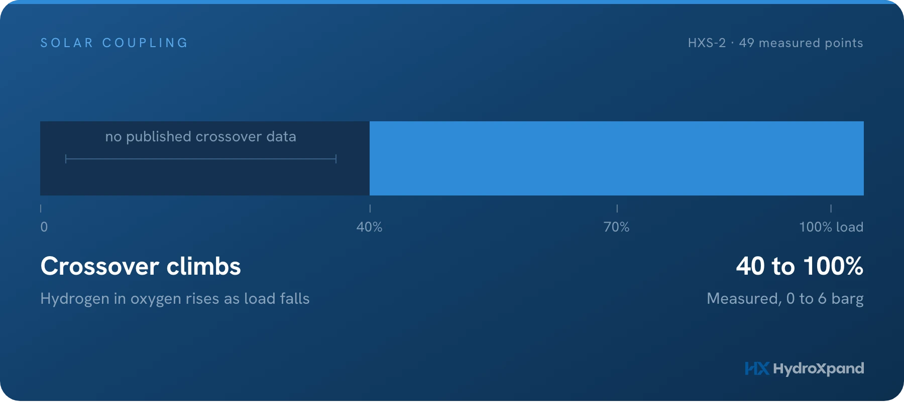
Put an electrolyzer behind a solar array and the input stops being a setting. It becomes a curve that starts at zero, peaks around the middle of the day and returns to zero, with weather cutting into it.
The question that gets asked first is usually about speed: can the stack follow that curve. The question that decides the design is the other one. How far down can the load go, and what stops you when it gets there.
It is not efficiency that stops you. Efficiency gets worse at low load and that is tolerable. What sets the floor is gas crossover, and crossover is a safety limit rather than an economic one.
Why low load is the difficult part, not the easy part
Intuition says a stack at low load is working less hard and is therefore safer. The measurement says the opposite, and the reason is a ratio rather than a quantity.
Hydrogen permeates the membrane driven by the partial pressure difference across it. That flux depends on pressure and temperature, and it does not fall away when you reduce the current. What does fall with current is the oxygen being produced on the other side.
So the numerator holds roughly steady while the denominator shrinks, and the concentration of hydrogen in the oxygen stream climbs. Add pressure and the numerator rises too. The two effects multiply.
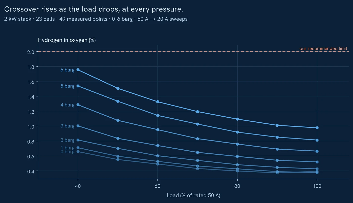
Those are our own measurements on a 2 kW stack, not a model. The four corners are the quickest way to read them.
The four corners
Raising pressure alone at rated load multiplies the figure by 2.5. Dropping the load alone at 6 barg multiplies it by a further 1.8. The corner where both meet is 4.5 times the ambient rated figure and leaves a quarter of a percentage point of headroom.
Read that as a design instruction rather than a warning. If your plan is ambient output into a buffer, the whole measured load range sits comfortably inside the limit. If your plan is pressurised output into storage, the minimum load becomes the first number to fix, before anything about the array.
| Hydrogen in oxygen | Rated load (50 A) | 40% load (20 A) |
|---|---|---|
| Ambient (0 barg) | 0.39% | 0.66% |
| 6 barg | 0.98% | 1.75%0.25 points below the 2% limit |
In a solar-coupled design the number to settle first is not response time. It is minimum load at the pressure you intend to run.
What our own system does, and what it does not
HXB-V1 runs from 15 to 67 A with 50 A recommended, and it delivers at 0 or 10 barg selected in software.
We do not present it as a renewable load-following product. It is built for steady operation, and a design that asks it to chase a swinging input is using it against its grain. That is a limitation of this product, stated here for the same reason it is stated on the product page.
There is also a boundary on our data that matters more than the specification. The crossover sweeps above run from 50 A down to 20 A, which is 40% of the recommended point. The current range goes lower than that, but we have not published crossover measurements below 20 A and you should not read the specification range as a safety envelope.
Pressure has the same kind of boundary. The sweeps cover 0 to 6 barg. The 10 barg on the datasheet is a pressure rating, and we have not published crossover across that last stretch.
- Measured crossover: 0 to 6 barg, 50 A down to 20 A.
- Specified operation: 15 to 67 A, 0 or 10 barg.
- These are two different statements. Ask any supplier which one they are quoting.
Three ways people bridge the gap, and what each one costs
None of these is exotic and all three are decided before the equipment is chosen, which is why they belong in this article rather than a commissioning manual.
A battery or grid tie between the array and the stack turns a variable input into a steady one. The stack then runs at a fixed point, which is the condition all of our published data describes. The cost is the buffer itself and the round-trip losses through it.
Running fewer hours at a good point instead of more hours at a bad one is the option people skip. If the profile spends its morning and evening below your floor, the stack can simply be off in those hours. Output falls with the hours, but every hour it does run sits inside the measured envelope.
Splitting the plant into smaller units lets you switch units on and off with the resource, keeping each running unit near its rated point rather than holding one large unit at 20%. That trades capital cost for operating range, and it is the reason our 30 kW stack is designed to be used in multiples.
What all three have in common is that they keep the stack away from the corner where pressure and low load meet. That corner is the thing being designed around.
What to check before committing to a design
- Fix the outlet pressure you actually need. Asking for pressurised output where ambient into a buffer would do spends your crossover headroom on nothing.
- Fix the minimum load you intend to run, then ask the supplier for measured crossover at that load and that pressure. A single figure at rated output does not describe an operating range.
- Ask how far the measured data extends, separately from how far the specification extends. These are rarely the same number.
- Decide whether the stack or the buffer absorbs the variability. That decision sizes both.
- Ask what happens on the way down and the way up. Start-up and shutdown cycles are a durability question, and a solar profile asks for one of each every day.
- Between one and fifteen kilograms a day→The other answer to a falling load: shut units down instead of turning one down.
- Do you need a compressor?→The same headroom, spent on pressure instead of turndown.
- Pressurised operation, measured→The 49 points behind this article, with the two 10 barg runs.
- HXB-V1 · 2 kW system→15 to 67 A, 0 or 10 barg. The full specification table.
- HXS-2 · 2 kW stack→The stack these measurements were taken on.
- Power to gas, and back again→What storing surplus renewable electricity as hydrogen costs at each step.
- Is AEM proven?→What a durability number has to carry before it means anything.
Frequently asked questions
Can an electrolyzer run directly on solar power?
It can follow the power, but the harder question is the minimum load. Gas crossover rises as load falls, and the floor is set by the hydrogen-in-oxygen safety limit rather than by efficiency.
What is the minimum load of an AEM electrolyzer?
HydroXpand measured 49 crossover points on the HXS-2 from 50 A down to 20 A and from 0 to 6 barg. At the worst corner, 6 barg and 40% load, crossover was 4.5 times the ambient rated value; the control limit is 2% hydrogen in oxygen.
What should be settled first in a solar-coupled design?
The minimum load at the pressure you intend to run, not the response time.
Looking at AEM for a specific application?