A laboratory that has made its own electrodes and membranes usually wants to stack them next, and that is where many projects stop. None of the four usual failure points is a materials problem. Each one shows up in the data in its own way, and the first job is to find out which one you have.
Once a laboratory can make its own electrodes and membranes, the next goal is usually to stack them. Performance that looked good in a single cell then goes missing when several cells are put together.
This is one of the most common reasons research groups contact us: the project calls for a large-area stack, the electrodes and membrane are made, and the build stops at assembly. Many laboratories try this and most stop at the same few places.
Below: where those places are, why a larger cell makes them harder, and what to build yourself versus hand over. We passed the same points developing our 30 kW stack, and the record is public.
Four places a stack build stops
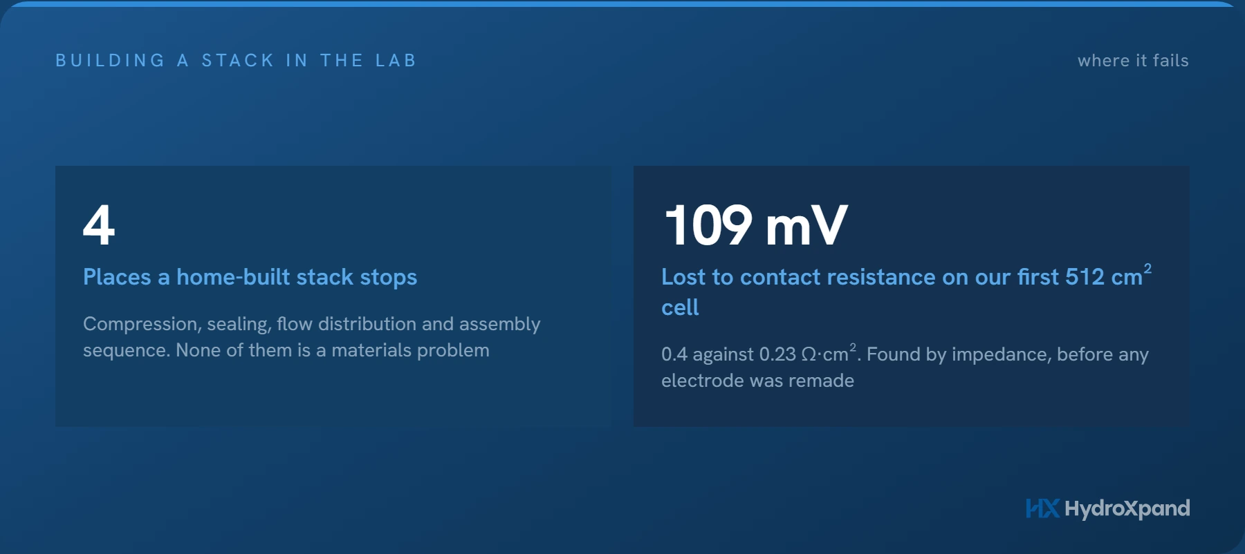
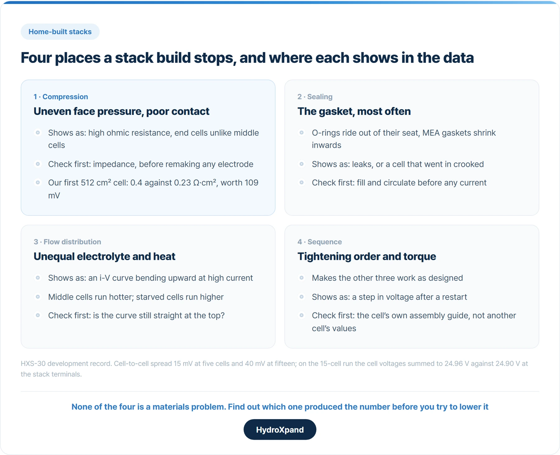
They are compression, sealing, flow distribution and assembly sequence. None of them is a problem with the electrode or the membrane. They are problems with how the cells are put together, and a single cell hides all four.
They can produce similar symptoms. A high cell voltage can come from poor contact, from a cell starved of electrolyte, or from a cell that went in crooked, so the useful question is which of the four produced it.
Two axes: more cells, and larger cells
Going from a cell to a stack moves along two axes. Adding cells is a question of assembly and uniformity, so you can predict where it will be difficult. Enlarging the cell changes what happens inside it: whether current spreads evenly over a wide face, whether electrolyte reaches the corners, whether bubbles get out. That you find out by running it.
Our own path shows both. The 2 kW HXS-2 is 23 cells with a 79 cm² cathode active area. The 30 kW HXS-30 is 46 cells with a 512 cm² cathode active area, on a 600 cm² anode against 100 cm² for the HXS-2.
Diagnose before you fix: the first large-area cell
The first 512 cm² cell we ran was poor. At 0.64 A/cm² it needed 1.925 V, where the HXS-2, already in commercial service, needs 1.645 V per cell at 0.633 A/cm².
If catalyst activity had been the cause, the electrode would have had to be remade. If resistance was the cause, only the cell hardware needed changing. The curve shape and the impedance together told them apart.
The large-area cell's ohmic resistance was 0.4 Ω·cm² against 0.23 Ω·cm² for the HXS-2. At 0.64 A/cm² that 0.17 Ω·cm² difference is 109 mV, much of the gap. The cause was electrical contact inside the cell: over a larger face, uniform compression decides the resistance. After a mechanical redesign, the HXS-30 five-cell short stack came down to 1.634 V per cell, and the electrode was never remade.
When a stack's first result is bad, find out which loss it came from before trying to reduce it.
What each failure looks like in the data
- Compression. One set of tie rods presses every cell, so face pressure differs between the middle and the ends, and contact resistance differs with it. End cells behave differently from middle cells, though not always in the same direction: in our HXS-30 15-cell run cell 1 was the highest, and in the 46-cell record cell 46 was the lowest, for a reason not yet established.
- Sealing. The gasket is the most common failure. O-rings ride out of their seat and the MEA gasket shrinks inwards, so both have to be pushed back into place after seating. Do not match gasket thickness to electrode thickness; a nickel-foam anode compresses a great deal, so try several and check leaks and performance.
- Flow distribution. One electrolyte stream splits among the cells, so each receives a different flow. Middle cells also have less path for heat to leave. Across a wide face, if electrolyte misses the corners or bubbles do not clear, the i-V curve bends upward at high current. The HXS-30 15-cell curve stayed straight.
- Sequence. Tightening order and torque are what make the other three work as designed. They belong to the specific cell and are given in its assembly guide; the electrode terminals have their own value, and over-tightening damages them.
As cell count rises, the number to follow is the spread between cells rather than the average. The HXS-30 spread was 15 mV at five cells and 40 mV at fifteen. At 46 cells it was 33.7 mV at the start of the long-run record and widened to 74.3 mV over the first 96.7 hours, which is why five even cells do not show that a stack is even.
- The first large-area cell performed worse than the stack we already sell→The full diagnosis, from the single cell through five and fifteen cells.
- The 46-cell full stack: first 96.7 hours→How the cell-to-cell spread moved at full cell count.
If you build it yourself, work in this order
Start from a test cell. HydroXpand's HXS-0 takes a gasket-defined active area of 1 to 25 cm² and builds from a single cell to a 20-cell short stack. It runs at up to 80 °C at atmospheric pressure. The lab supplies power, electrolyte circulation, temperature control and data logging; a programmable supply suits wide sweeps.
- Assemble to the guide. HXS-0 closes with M6 bolts and needs no press, and the tightening order and torque come in its assembly guide. Gaskets and other consumables are supplied separately.
- Fill and check for leaks before current. Fill the tank, circulate, check every joint, then watch voltage, leaks, temperature and gas release on the first run.
- Measure every cell separately. If the cell voltages add up to the stack voltage, the measurement can be trusted. On the HXS-30 15-cell run they summed to 24.96 V against 24.90 V at the stack terminals.
- Stop and restart, and see whether the voltage returns to its trend. Compression loosening in operation leaves a step. The HXS-30 15-cell stack went through four stops and restarts in 293 hours, and each returned to the existing trend.
Such deviation also depends on the in-stack positions of the terminals across which the individual cell voltages and the stack voltage are measured.
To set your results beside published data, match current density, active area, temperature, electrolyte concentration, pressure, membrane thickness and the initial stabilisation period. A voltage from a different cell size or test rig is not directly comparable.
What to build yourself and what to hand over
Three things decide it: whether you have a press, how many cells and how much area, and whether you can match conditions for a comparison.
Electrodes, membranes, MEAs and single-cell or short-stack evaluation belong in the lab. That is where the materials research is.
Large-area and high-cell-count full stacks are better handed over. From the 2 kW stack upward, assembly is by compression: a hydraulic press, a dedicated EPDM gasket set and a fixed compression and bolting sequence. Those settings belong to that stack and do not carry over to a cell. If you need to open one and have no press, tell us before you open it and we will work out an approach.
| Build it in the lab | Hand it over | |
|---|---|---|
| Scope | Electrodes, membranes, MEAssingle cell and short stack | Large-area or high-cell-count full stack |
| Assembly | Bolted by handHXS-0: M6, no press | Compression assembledhydraulic press, EPDM gasket set |
| Variables | Few cells, small areafaults are easy to isolate | Compression and flow effects growwith cell count and area |
| Comparison | Against your own reference cell | Against published dataneeds matched conditions and equipment |
Build what your research is about. Hand over the parts where assembly, not material, decides the result.
- What is an electrolyzer stack→Why compression, flow and repeated interfaces matter, explained from first principles.
- Choosing an AEM test cell→Sample fit, surrounding equipment and a repeatable reference test.
- HXS-0 · 1–25 cm² test cell→Single cell to 20-cell short stack, assembled without a press.
- Stack hardware→Bipolar plates, gaskets and end plates, and how the clamping load is set.
- The 15-cell short stack ran for 293 hours→Four stops and restarts, each back on the trend line.
Frequently asked questions
Why does performance drop when I stack electrodes that worked in a single cell?
A stack adds variables a single cell does not have: compression, sealing, flow distribution and assembly sequence. Separate a resistance problem from a catalyst problem with the i-V curve and impedance, then measure each cell's voltage.
How many cells can the HXS-0 test cell stack?
From a single cell to a 20-cell short stack, with an active area of 1 to 25 cm² set by the gasket window.
Can I assemble a stack without a press?
The HXS-0 test cell closes with M6 bolts and needs no press. From the 2 kW stack upward, assembly is by compression and needs a hydraulic press and a dedicated gasket set.
Sources
- EU harmonised accelerated stress testing protocols for low-temperature water electrolyser, EUR 31748 EN — European Commission Joint Research Centre, 2024
Looking at AEM for a specific application?