The anode with the best initial polarisation curve is not necessarily the most stable over long operation. The degradation mechanisms of particle-based and grown catalyst layers, the limits of published durability data, and what to check when selecting and testing an anode.
Electrodes are usually compared by assembling a test cell and measuring a polarisation curve, the cell voltage as a function of current. A lower cell voltage at a given current is taken as better performance. This curve, however, reflects the cell immediately after assembly. It does not show whether the ranking will hold after hundreds or thousands of hours of operation.
This article covers how the method used to form the anode catalyst layer affects long-term behaviour, and what to check when selecting and testing an anode. The supporting data are in our anode durability note.
- Treat the polarisation curve from a freshly assembled cell as a measure of initial performance. It reflects the active surface area of the catalyst, not how securely the catalyst layer is fixed to the substrate.
- Check how the catalyst layer was formed. Layers of catalyst particles held by a binder and layers grown directly on the substrate degrade by different mechanisms.
- Look at the rate of cell-voltage rise at constant current. Long-term stability is assessed from the voltage change during operation, not from the initial value.
- Compare anodes in the same cell build. A different membrane or different operating conditions can change the result for the same anode considerably.
The reaction at the anode
In an electrolysis cell, hydrogen is produced at the cathode and oxygen at the anode. The oxygen evolution reaction (OER) at the anode is kinetically slow and carries a large overpotential, so the anode catalyst has a strong influence on cell voltage.
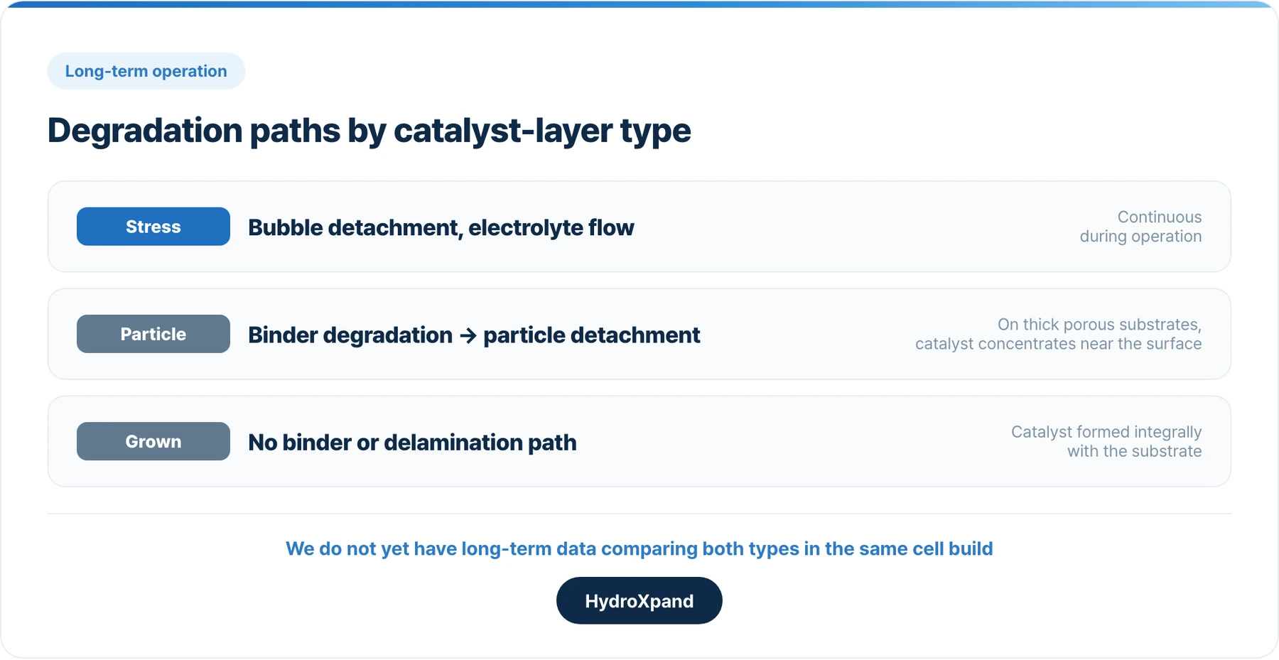
During operation, oxygen bubbles form and detach from the anode surface continuously, and electrolyte flows across it. Both impose sustained mechanical stress on the catalyst layer. Anode durability depends on how long the catalyst layer keeps its activity and electrical contact under these conditions.
Two ways to form the catalyst layer
| Type | Fabrication | How the catalyst is fixed |
|---|---|---|
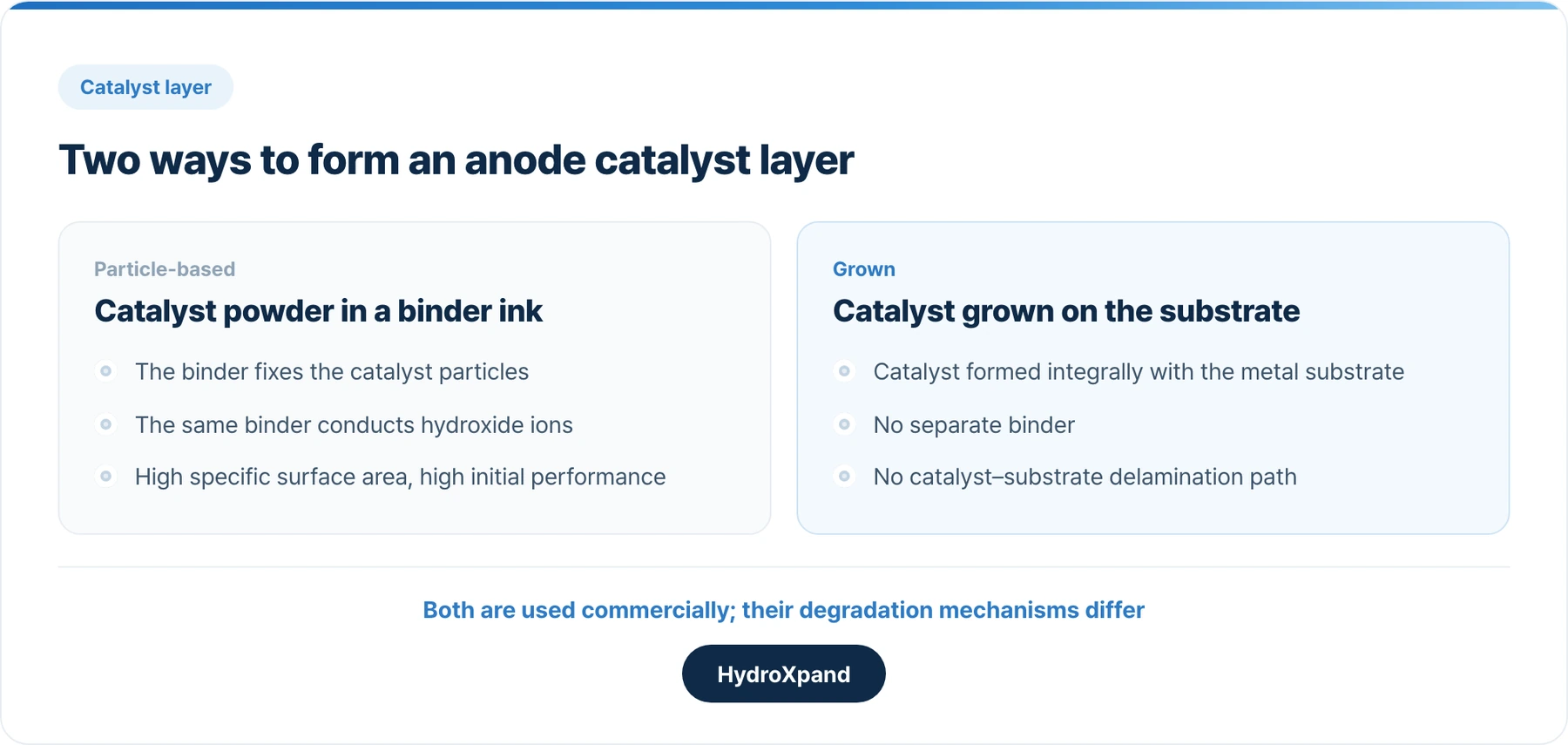
| Particle-based | Catalyst powder is mixed with a binder (ionomer) into an ink and applied to the substrate | By the binder |
| Grown | Catalyst is grown directly on the substrate surface | Formed integrally with the substrate metal; no separate binder |
Both types are used in commercial products; particle-based layers are the more common.
Initial performance is often higher for particle-based anodes
Immediately after assembly, particle-based anodes often show higher performance. Finely milled catalyst powder has a high specific surface area, and the ink formulation can be optimised to raise the initial current density.
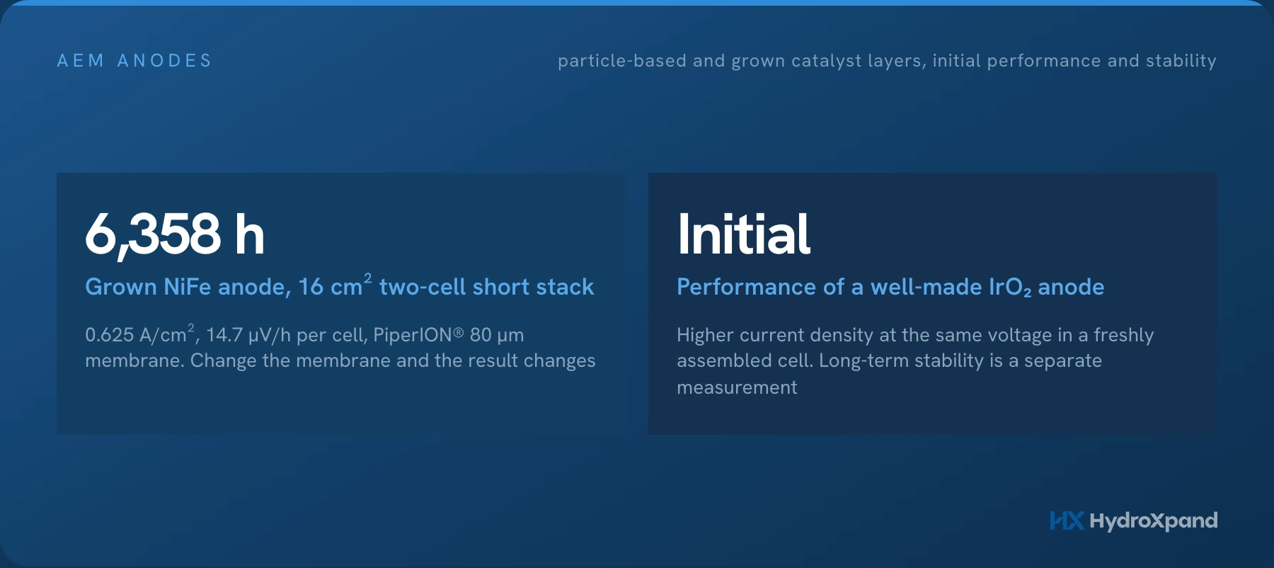
Particle-based anodes with precious-metal catalysts such as iridium oxide (IrO₂) in particular deliver a higher current density at the same cell voltage. Our anode also shows a lower current density than such anodes immediately after assembly.
Differences in long-term operation
In a particle-based layer, the binder both fixes the catalyst particles and conducts the hydroxide ions (OH⁻) the reaction needs. Repeated stress from bubble detachment and electrolyte flow degrades the binder, and catalyst particles gradually detach. Particles that remain in place no longer take part in the reaction once their electrical contact with the substrate deteriorates.
Coating uniformity becomes an issue as electrode area increases. Porous substrates several millimetres thick are difficult to coat uniformly throughout, so the catalyst concentrates near the surface, which is also where stress from bubbles and flow is highest.
In a grown layer, the catalyst is formed integrally with the substrate metal, and with no binder there is no catalyst detachment caused by binder degradation.
What 377 published durability records show
From the 756 AEM water electrolysis papers we have collected, we took the 404 that report cell durability tests and compiled the constant-current cell and stack tests each paper performed itself. Half-cell tests, results cited from other work, ion-solvating PBI membranes and bare substrates without a catalyst were excluded, and the catalyst-layer form was classified from each paper's experimental section. That leaves 377 constant-current records.
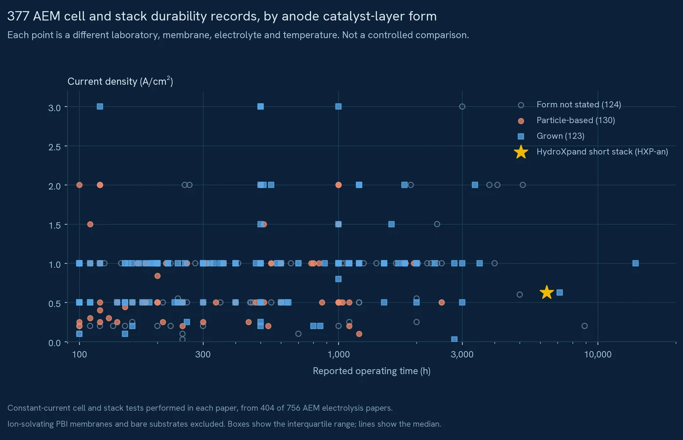
The longest runs all used grown anodes: 14,000 hours at 1 A/cm² (12.3 µV/h), 7,130 hours in a two-cell stack at 0.625 A/cm² (38.5 µV/h) and 3,500 hours at 1 A/cm² (25 µV/h). The longest particle-based run was 2,500 hours at 0.5 A/cm². Most tests ended at a planned time, so the rate of cell-voltage rise is a better basis for comparison than operating time.
Splitting the records that report a degradation rate by current-density band, the median for grown anodes is lower than for particle-based anodes in all three bands, at 35–58% of the particle-based value.
| Current density | Particle-based, median | Grown, median |
|---|---|---|
| 0.6 A/cm² or below | 400 µV/h (29 records) | 140 µV/h (11 records) |
| Above 0.6, up to 1.0 A/cm² | 104 µV/h (41 records) | 60 µV/h (31 records) |
| Above 1.0 A/cm² | 132 µV/h (7 records) | 76 µV/h (4 records) |
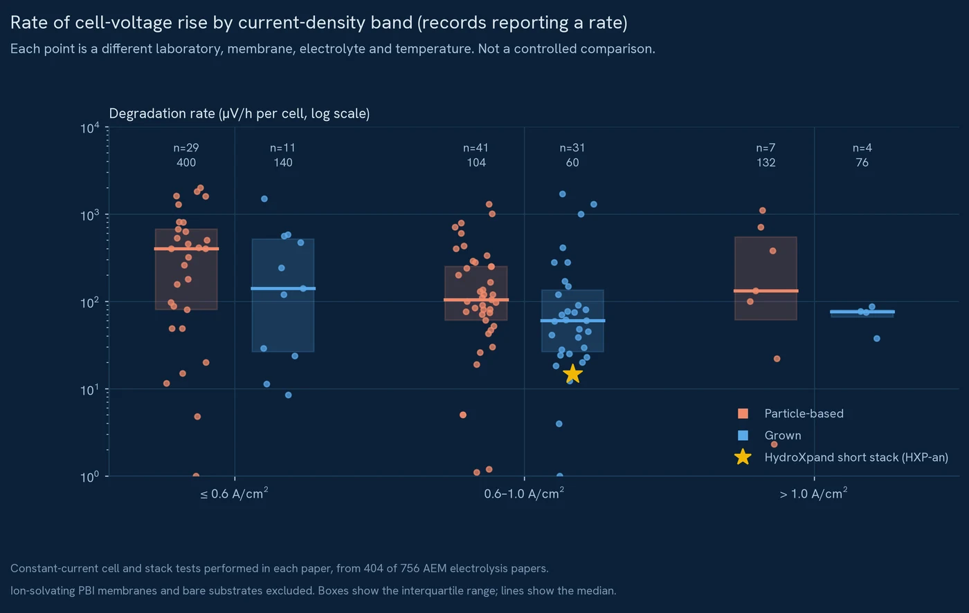
Because the particle-based group includes iridium oxide and several other catalysts, we also compared nickel-iron anodes on their own. The same trend held: a median of 70 µV/h for grown anodes against 117 µV/h for particle-based ones.
Across the published AEM durability records, grown anodes showed a lower rate of cell-voltage rise than particle-based anodes, and the longest runs all came from grown anodes. This is consistent with their structure, which has no binder to degrade and release the catalyst. It is why we make our anodes as grown layers.
Membranes and operating conditions differ between studies, so this is not a controlled comparison. We will publish results comparing the two forms in the same cell build when we have them.
- Anode durability note→The degradation mechanism and our short-stack run.
What to check when selecting and testing an anode
| Item | Reason |
|---|---|
| Catalyst layer type | Particle-based and grown layers degrade by different mechanisms |
| When the polarisation curve was measured | A value from a freshly assembled cell means something different from one after a period of operation |
| Rate of cell-voltage rise at constant current | Comparable between tests of different duration; check the fitting window as well |
| Cell voltage at the end of the test | A long test that ended at a high voltage is assessed differently |
| Membrane and operating conditions | The result for the same anode can change considerably with a different membrane |
The membrane has a particularly large effect. In short-stack tests with our anode, changing only the membrane changed the operating time by a factor of about five. This example, and how to interpret durability data, are covered in our article on durability data.
When testing yourself, we recommend operating at constant current in the same cell build and conditions and following the cell voltage, rather than judging from a single polarisation curve. If your measurements differ from the datasheet, our article on test results lists what to check.
- Reading electrolyzer durability data→Hours, degradation rate and the conditions behind them.
- When your test results differ from the datasheet→Seven things to check before comparing with a reference curve.
Our anode
Our anode, HXP-an, is a nickel-iron catalyst grown directly on a nickel foam substrate, with no binder and no platinum-group metal. The structure was chosen for long-term stability and cost rather than initial performance.
A 16 cm² two-cell short stack built with this anode and a PiperION® 80 µm membrane operated for 6,358 hours at a constant 0.625 A/cm². Over this period the cell voltage rose from 1.893 V to 1.979 V, a rate of 14.7 µV/h per cell from a linear fit over the entire run. Results may differ with other membranes and operating conditions.
The 7,130-hour record above comes from a KAIST study in which our CEO is a co-author (Advanced Science, 2026). It used a nickel-iron oxyhydroxide anode formed on nickel foam during operation, in a two-cell stack at 0.625 A/cm². It is an academic result and separate from the test record of our HXP-an product.
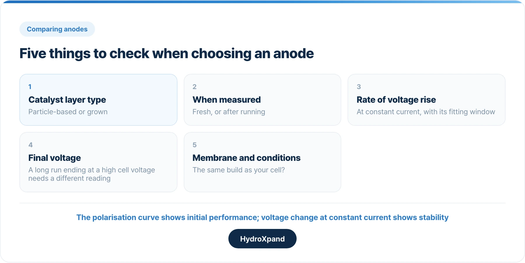
Five things to check when comparing anodes
- Whether the catalyst layer is particle-based or grown
- Whether the polarisation curve was measured right after assembly or after operation
- The rate of cell-voltage rise at constant current and its fitting window
- The cell voltage at the end of the test
- Whether the membrane and operating conditions match your cell
Frequently asked questions
Isn't the anode with the better polarisation curve the better anode?
A polarisation curve from a freshly assembled cell reflects initial catalyst activity well, but not how securely the catalyst layer is fixed to the substrate. For long service, also check the rate of cell-voltage rise at constant current.
Should particle-based anodes be avoided?
No. Particle-based anodes are widely used commercially and can suit applications where initial performance matters most. Their degradation mechanism differs, so choose according to the service period and operating conditions.
Is performance lower without iridium?
Immediately after assembly, iridium oxide anodes show a higher current density at the same cell voltage. In the published AEM durability records, the median rate for iridium oxide anodes was about 320 µV/h against about 80 µV/h for iridium-free anodes. Every iridium oxide record was 2,000 hours or shorter, and iridium-free anodes have run longer. The choice depends on whether initial performance or long-term stability takes priority.
Do you have data comparing particle-based and grown anodes under the same conditions?
Among the 123 published AEM constant-current records that report a degradation rate, the median rate of cell-voltage rise for grown anodes was 35–58% of that for particle-based anodes in each current-density band. Conditions differ between studies, so it is not a controlled comparison. We will publish our own comparison in the same cell build when we have it.
Looking at AEM for a specific application?